Indoor Unit Operation & Installation Manual MVAD007MV2AA MVAD009MV2AA MVAD012MV2AA MVAD018MV2AA MVAD024MV2AA No. 0150519177 • Please read this manual carefully before using. • Keep this operation manual for future reference.
User Manual CONTENTS Parts and Functions ����������������������������������������������������������������������������������������������������������������������������������������������������������1 Safety ��������������������������������������������������������������������������������������������������������������������������������������������������������������������������������2 Maintenance ����������������������������������������������������������������������������������������������������������������������
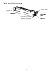
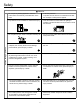
Parts and Functions Hanging bracket Supply air Liquid and vapor ports Drainage pipe (gravity) 1
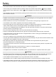
Safety • This manual should be saved and stored close to this air conditioning equipment. • There are two types if indications. Both are related to safety and should be strictly followed. " Warning" highlights issues that pose a risk of major injury or death. " Caution" highlights issues that pose a risk of equipment or bodily injury. • After installation and start-up commissioning, please give the manual to the user. The manual should be kept in safe place and close to the unit.
Safety Notices during Operation Attention • Do not put any heating apparatus under the indoor units. The heat may cause distortion of the units. • 3-minutes protection To protect the unit, there is a 3-minute time-out after the unit stops or after power is applied. • Pay attention to the ventilation to avoid anoxic injury. • Close the window to avoid outdoor air getting in. Curtains or window shutters can be put down to avoid the sunshine. • Do not place an open flame in the path of blowing air.
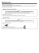
Maintenance Cleaning the air filter & air inlet grid. • Don't remove the air filter except for cleaning, or faults may occur. • When the air conditioner operates in the environment with too much dust, clean the air filter on a more regular basis (generally once every two weeks). Cleaning the Air Inlet/Outlet Grilles: Attention • Do not use gasoline, benzene, diluents, polishing powder or liquid insecticide to clean them. • Do not clean them with hot water of over 122°F(50°C) to avoid fading or distorting.
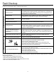
Fault Checkup Please make another check. All these are not problems Please check the following when consigning repair service: Symptoms Reasons Water flow sound Water flow sound can be heard during starting operation, during operation or immediately after stopping operation. When it starts for 2-3 minutes, the sound may become louder, which is the flowing sound of refrigerant or the draining sound of condensate water.
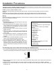
Installation Procedures This manual cannot completely illustrate all the properties of the products you bought. Please contact the local Haier distribution center if you have any question or request. Caution: Choose a suitable installation location. Avoid places with high salinity (salt water) and high sulfur gas. Unit will corrode and damage will not be covered by warranty. Avoid excess oil (including mechanical oil) and steam. This can reduce efficiencies and product performance.
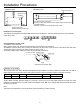
Installation Procedures Dimension (unit: in.). a 16.5 16.5 b 35.1 47.7 c 14.6 14.6 d 33.5 46.1 e 7.3 7.3 f 25.2 37.8 b g 3.6 3.6 h 29.9 42.5 i 6.0 6.
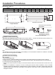
Installation Procedures ˃40in (1000mm) Installation space ˃4in(100mm) Installation mode 4-Ø3/8"(M10)hanging bolt Electric control enclosure 8-Ø3/8"(M10) nut 8-Ø3/8"(Ø10) Washer Level the unit within 0.2in(5mm). If end A is to drain water, ensure end B is slightly higher than the end A to facilitate drainage. Otherwise, ensure end A is slightly higher than end B.
Installation Procedures Installation of drain hose Connection of indoor drain hose 1. Please use the accessory drain hose to connect indoor unit's water outlet and PVC pipe. Use snap rings to tighten them as shown in the following figure: 2. Please use rigid PVC adhesive for connection of other pipes and ensure there is no leakage. 3. Drain hose must be wrapped with insulation sleeve and tightened with a strap to prevent air leakage from producing condensate. 4.
Installation Procedures Pipe Length & Height Difference Please refer to the attached manual of outdoor units. Model Tubing Size in(mm) Tubing Material MVAD007~018MV2AA MVAD024MV2AA Gas pipe Ø1/2"(Ø12.7) Ø5/8"(Ø15.88) Liquid pipe Ø1/4"(Ø6.35) Ø3/8"(Ø9.52) Seamless copper pipe rated for R410A refrigerant Tubing Materials & Specifications Special tools for R410A should be used for cutting and enlarging pipes.
Electrical Wiring WARNING • Follow local codes when selecting wire gauge and connecting to house power. • Use the cable strain relief clips and locking conduit clamps to prevent wires from being pulled off terminal posts. • Unit must be properly grounded. Do not use water or gas piping, phone ground or lightning rod. Attention • Only copper wire can be used. A properly sized breaker should be provided, or electric shock may occur. • Unit requires 220VAC - 2 voltage wires and a ground. No neutral.
Electrical Wiring Signal Wiring Drawing Outdoor PQA B C Communication wire between indoor & outdoor without polarity Indoor 1 (950 CASSETTE) Indoor 3 Indoor 2 A BC PQ Control wire for wired controller with polarity PQA B C PQA B C A BC Indoor 5 Indoor 4 PQA B C A BC Indoor 7 Indoor 6 PQA B C A BC Wired controller A BC PQA B C Wired controller PQA B C Wired controller A BC Wired controller Indoor 9 Indoor 8 PQA B C Wired controller A BC PQA B C Wired controller A BC A BC Wired co
Electrical Wiring Wire gauge size and breaker size for total indoor amp draw. Current NEC guidelines and local codes will trump this chart. Items Total Current of Indoor Units(A) <7 ≥7 and <11 ≥11and <16 ≥16 and <22 ≥22 and <27 • • • • • Cross Section AWG (mm2) Length in.(m) Rated Current of Overflow Breaker(A) Rated current of residual Circuit Breaker(A) Ground Fault Interrupter(mA) Response time(S) Cross Sectional Area of Signal Line 14(2.5) 12(4) 10(6) 8(8) 6(10) 65.6(20) 65.6(20) 82(25) 98.
Electrical Wiring Dipswitch Setting • The dip switch is set to the "On" position if “1” is indicated in the table. The dip switch is set to the "Off" position if "0" is indicated in the table. • Dip switches set in the factory to on are marked with red. Definition principles of code switches: (A) Definition of SW01: SW01_1-4 is used to set indoor address when grouping multiple indoor units connected to single wired controller YRE16B or YR-E17. SW01_5-8 set capacity of the indoor unit (factory set).
Electrical Wiring (B) Definition and description of SW03 SW03_1-8 is used to set indoor unit address on system. Set address only if using central controller YCZ-A004. Leave default if no central controller is used.
Electrical Wiring Dip Switch Setting of YR-E17 Wired Controller Function switches DIP switch Sw1 Sw2 Sw3 Sw4 Sw5 Sw6 Sw7 Sw8 On/Off station On Off On Off On Off On Off On Off On Off On Off On Off Function Slave wired controller Master wired controller Ambient temp. display on Ambient temp. display off Collect ambient temp. from PCB of indoor Collect ambient Temp.
Test Run & Failure Code Before Test Run • Connect it to the power supply of the outdoor units to energize the heating belt of the compressor. To protect the compressor at startup, power it on 12 hours prior to the operation. Check if the connections of the drainpipe and wire connection lines are correct. The drainpipe shall be placed at the lower part while the connection line placed at the upper part.
Qingdao Haier Air Conditioner Electric Co.,Ltd. Haier Industrial Park,Qianwangang Road,Eco-Tech Development Zone,Qingdao 266555, Shandong,P.R.C.