MINI 4-way Cassette Service Manual SYJS-07-2017 REV.
CONTENTS 1. Feature.....................................................................................................................................1 2. Specification.............................................................................................................................2 3. Dimension................................................................................................................................5 4. Piping diagram........................................................
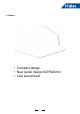
1.
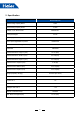
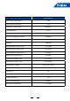
2.
MVAB012MV2AA Rated Cooling Capacity Btu/hr 12,000 Rated Heating Capacity Btu/hr 13,500 Voltage, Cycle, Phase V/Hz/- 208/230-60-1 Fan Speed Stages 3+Auto Airflow (High/Med/Low) CFM 700/590/480 Motor Speed (High/Med/Low) RPM 760/650/520 Indoor Sound Level dB (High/Med/Low) 32/30/29 Grill Model PB-620KB Chassis Dimension: Height in (mm) 10 1/4 (260) Chassis Dimension: Width in (mm) 22 7/16(570) Chassis Dimension: Depth in (mm) 22 7/16(570) Grill Dimension: Height in (mm) 2 3/8 (60) Gril
MVAB018MV2AA Rated Cooling Capacity Btu/hr 19,000 Rated Heating Capacity Btu/hr 21,000 Voltage, Cycle, Phase V/Hz/- 208/230-60-1 Fan Speed Stages 3+Auto Airflow (High/Med/Low) CFM 700/590/480 Motor Speed (High/Med/Low) RPM 760/650/520 Indoor Sound Level dB (High/Med/Low) 33/30/29 Grill Model PB-620KB Chassis Dimension: Height in (mm) 10 1/4 (260) Chassis Dimension: Width in (mm) 22 7/16(570) Chassis Dimension: Depth in (mm) 22 7/16(570) Grill Dimension: Height in (mm) 2 3/8 (60) Gril
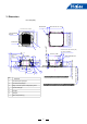
3. Dimension Unit: inch(mm) Indoor unt 22 . 7/16(570) less than100 connect drain pipe 60 . . Indoor unt 22 7/16(570) Ceiling open 23 . 1/4(590) decoration board 24 7/16(620) pipe connection diagram 21 1/16(535)(gap betweensupending rods) ⑦ decoration board 24 7/16(620) ⑥ . less than 1/2(10) 6 3/4(170) . 8 1/4(210) . 12 1/4(310) . 5 1/2(140) 1 1/4(30) .
TC2 Filter EEV Fan M TA Filter Indoor heat exchanger TC1 6 (Flared joint) Liquid pipe (Flared joint) Gas pipe 4.
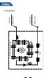
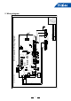
3 Controller Wire 2 CN16 G 7 Display Board 10 10 Y LED6 CN26 R 485-PC MAIN BOARD LED3 LED4 SW03 CN41 WH SW01 WH Swing2/3 PMV G Tc1 Tc2 TA B WH P Q 2 Communication With Outdoor 3 PUMP CN1 WH CN8 M DC FAN N Y/R LED1、2 Wire Controller With Indoor Unit LED3、4 Indoor Unit &Outdoor Unit LED5 Error Indicate LED Definition AC220V L BR(R) BL(B) 5 Wired Controller A B C T5A/250VAC WH WH CN33 L-TXD WH RELAY CN4 CN35 CN5 Y WH G CN38 CN17 CN20 WH WH WH R R BL CN11-1 CN11 CN
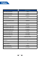
6. Electric characteristics Units Power supply Model Phase FQY Voltage MVAB009MV2AA MVAB012MV2AA MVAB018MV2AA 1 1 1 50/60 50/60 50/60 220 220 220 Volt. range 198~242 198~242 198~242 MCA MFA 0.325 0.325 0.325 1.04 1.04 1.04 Indoor fan motor Output (W) 26 26 26 FLA Power input (w) Cooling Heating 0.26 0.26 0.26 Symbols: MCA: Min. circuit amps (A) MFA: Max. fuse amps of circuit breaker Output: Fan motor rated output (w) FLA: Full load amps (A) Note: 1.
7. Air velocity and temperature distribution a. Cooling / Air velocity distribution Cooling Blowy angle: 40 Air velocity distribution 2.7m 2m 1.5m/s 1.5m/s 1.0m/s 1.0m/s 1m 0.5m/s 0.5m/s 4m 3m 2m 1m 0m 1m 2m 3m 0m 4m b. Cooling / Temperature distribution Cooling Blowy angle: 40 Temperature distribution 2.
c. Heating / Air velocity distribution Heating Blowy angle: 70 Air velocity distribution 2.7m 2m 1.5m/s 1.5m/s 1.0m/s 1.0m/s 1m 0.5m/s 0.5m/s 4m 3m 2m 1m 0m 1m 2m 3m 4m 0m d. Heating / Temperature distribution Heating Blowy angle: 70 Temperature distribution 2.
8. Sound pressure level 1.5M 1) Testing illustrate: 2) Testing condition: a: Unit running in the normal condition b: Test in the semi-anechoic chamber c: Noise level varies from the actual factors, such as room structure, etc.
9. Installation 9.
9.2 Safety • This manual should be saved and stored close to this air conditioning equipment. • There are two types if indications. Both are related to safety and should be strictly followed. " Warning" highlights issues that pose a risk of major injury or death. " Caution" highlights issues that pose a risk of equipment or bodily injury. • After installation and start-up commissioning, please give the manual to the user. The manual should be kept in safe place and close to the unit.
Notices during Operation Attention • Do not put any heating apparatus under the indoor units. The heat may cause distortion of the units. • 3-minutes protection To protect the unit, there is a 3-minute time-out after the unit stops or after power is applied. • Pay attention to the ventilation to avoid anoxic injury. • Close the window to avoid outdoor air getting in. Curtains or window shutters can be put down to avoid the sunshine. • Do not place an open flame in the path of blowing air.
9.3 Maintenance Attention • Repair can only be performed by licensed service technicians. • Before touching the electrical connections, all power supplies should be turned off. Only after switching off the power supply can the operator clean the air conditioner otherwise there is a risk of electric shock or injury. • When cleaning the air cleaner, make sure to use a stable platform; don't flush the air conditioner with water, or electric shock might occur.
Installing air cleaner and air inlet grid: 1. Mounting the filter: opposite of dismantling the filter (as shown in Fig. 3 above). 2.Mounting the air inlet grid: as shown in the right figure, clip the locks on the grid as directed by the arrows, put the side with the hinges into the lock port, and then put the side with locks into the panel frame. Release the locks to position the grid after determining that the grid is flush with the bottom of the panel frame.
9.4 Fault Checkup Please make another check. All these are not problems Please check the following when consigning repair service: Symptoms Reasons Water flow sound Water flow sound can be heard during starting operation, during operation or immediately after stopping operation. When it starts for 2-3 minutes, the sound may become louder, which is the flowing sound of refrigerant or the draining sound of condensate water.
9.5 Installation Procedures Caution: Choose a suitable installation location. Avoid places with high salinity (salt water) and high sulfur gas. Unit will corrode and damage will not be covered by warranty. Avoid excess oil (including mechanical oil) and steam. This can reduce efficiencies and product performance. Avoid areas where machines generate high frequency electromagnetic waves. They can cause control issues. Warning: protect the machine from winds or earthquake, install according to regulations.
indoor unit 22.4in(570mm) decorated board 24.4in(620mm) ceiling 23.2in(590mm) indoor unit 22.4in(570mm) gap between studs 21in(535mm) The ceiling and decorated board overlapping part should be more than 0.98in(25mm) ceiling decorated board 1.2in (30mm) 5.9in (150mm) decorated board 24.4in(620mm) 10.2in (260mm) ceiling 23.
Attention • For proper drainage, the drainpipes should be connected according to the installation manual. • Insulate the drainpipes to prevent exterior condensation. • Follow local plumbing codes when connecting drainpipes. Requirements: • The drainpipe of the indoor unit should be insulated. • Maintain a downward slope. Avoid waves or dips. • The horizon length of the drainpipe should be kept with 65.6ft(20m). Under the condition of long pipes, supports can be provided every 4.9-6.6ft(1.
Test the drainpipe to confirm that there are no leaks or other issues with the drainpipe. • After system is fully installed and power is applied, turn on cooling operation and add water to check for drainage. • Confirm sound from the motor of the drainage pump and check for proper drainage. 3.9in(100 mm) below joint of drainpipe lifting 23.
Installing the decorated panel on the body of indoor unit: receiving window for remote control the lamp will not flash when wired controller is used • Prior to attaching the panel to the unit locate the louver motor connector on the panel and the unit. Orientate the panel so they can connect. • First temporarily position it with screws. • Tighten each screw a little at a time to allow the panel to seat flush against the unit.
9.6 Electrical Wiring WARNING • Follow local codes when selecting wire gauge and connecting to house power. • Use the cable strain relief clips and locking conduit clamps to prevent wires from being pulled off terminal posts. • Unit must be properly grounded. Do not use water or gas piping, phone ground or lightning rod. Attention • Only copper wire can be used. A properly sized breaker should be provided, or electric shock may occur. • Unit requires 208/230VAC - 2 voltage wires and a ground. No neutral.
Signal Wiring Drawing Outdoor PQA B C Communication wire between indoor & outdoor without polarity Indoor 1 (950 CASSETTE) Indoor 3 Indoor 2 A BC PQ Control wire for wired controller with polarity PQA B C PQA B C A BC Indoor 5 Indoor 4 PQA B C A BC Indoor 7 Indoor 6 PQA B C A BC Wired controller PQA B C Wired controller A BC PQA B C Wired controller A BC Wired controller Indoor 9 Indoor 8 PQA B C Wired controller A BC PQA B C Wired controller A BC A BC Wired controller Wired con
Wire gauge size and breaker size for total indoor amp draw. Current NEC guidelines and local codes will trump this chart. Items Total Current of Indoor Units(A) <7 ≥ 7 and <11 ≥ 11and <16 ≥ 16 and <22 ≥ 22 and <27 • • • • • Cross Section AWG (mm2) Length in.(m) Rated Current of Overflow Breaker(A) Rated current of residual Circuit Breaker(A) Ground Fault Interrupter(mA) Response time(S) Cross Sectional Area of Signal Line 14(2.5) 12(4) 10(6) 8(8) 6(10) 65.6(20) 65.6(20) 82(25) 98.
10.
11. Dip switch setting Definition principles of code switches: SW01 is used to set wire controlled address of and set capabilities of master; SW03 is used to set indoor unit address (combine original communication address and address of centralized controller).
Special function 1. Emergency switch: Press the emergency switch in stop condition, indoor unit operate with AUTO, AUTO SPEED, 24 Setting modes, pressure the emergency switch in start condition, indoor unit will stop operation. 2. Temp. compensation: The heating mode, the temp. compensation range is -14 ~ 0 . Set the temp. compensation in Heating mode with remote controller, heating mode, set 30 as the reference point, press the sleep butter 7 times, the buzzer ring 2 times, the unit enter temp.
12. Indoor unit control 12.1 Cooling operation Set temp. in cooling: Ts=set temp. wired controller; After startup, indoor unit will send the request to outdoor according to the temp. difference between the set temp. and the room temp. 12.2 Heating operation Set temp. in heating: Ts=set temp. wired controller + TA correcting value. After startup, indoor unit will send the request to outdoor according to the temp. difference between the set temp. and the room temp. 12.3 Dry operation Room temp. - set temp.
12.8 Anti-freeze protection In cooling mode, execute the anti-freeze protection due to the measured indoor coil temp. to avoid the indoor heat exchanger causing frost or ice. 12.9 Swing motor control Indoor will control swing motor ON/OFF due to the swing signal from wired controller. 12.10 Auxiliary electric heater control In heating mode, if the below conditions can be met, the electric heater will work: (1) Indoor fan motor and compressor are running; (2) Air inlet temp.
13. Failure code Failure code PCB LED5(Indoor at wired Units)/ Receiver Timer Fault Descriptions controller Lamp(Remote Controller) 01 1 Fault of indoor unit ambient temp. transducer TA 02 2 Fault of indoor unit pipe temp. transducer TC1 03 3 Fault of indoor unit pipe temp. transducer TC2 04 4 Fault of indoor unit dual heat source temp.
14.
[05] EEPROM failure No If the chip is fixed well Reconnect Yes Yes If the chip is damaged Replace it No Check if PCB is faulty, if yes, replace it [09] Indoor address repeated No If wiring between P and Q is normal Modify the wiring Yes Yes If communication wire is connected with multi outdoors wire No If indoor QTY connected with outdoor is normal Modify the communication No Yes Check outdoor connecting board,if faulty, replace it 33
[06] Communication circuit between indoor and outdoor If wiring between P and Q is wrong or broken down Yes Modify the communication wire No If the port of CN15 on indoor PCB is normal No Modify the port Yes If the port of CN19 on outdoor connecting board is normal No Yes Yes If outdoor power source is normal Electrify the outdoor No Yes If power supply is failure Clear the failure code No Yes If there is noise No Check outdoor PCB, if faulty, replace it 34 Check and eliminate noise
[07] Communication abnormal between indoor and wired controller If wiring of terminal A, B, C of wired controller is proper No Modify the wiring Yes If the broken wire or port is fixed improperly Yes Modify the connection No If in group operation No If there is indoor unit set as No. 0 If there are multi indoors set as No. 0 If there is indoor unit set as No. 0 No No No Yes Set one indoor unit as No. 0 Set only one indoor unit as No. 0 Set one indoor unit as No.
[12] No 50Hz zero passage signal No Check if the transformer is well Replace transformer Yes Check if the wiring of the wired controller connect well Yes Replace PCB 36 No Reconnect
[14] DC motor failure Check if the wiring of motor is fixed well No Reconnect Yes Yes If the motor is fault No Replace the PCB 37 Replace motor
[18] The 4-way valve of 3-pipe valve box reversing failure If the 4-way valve of 3-pipe valve box is internal leakage Yes Adjust it correctly by after-sales personnel on site. No Check if the TC1 and TC2 of indoor unit are normal, if the resistance is right? If the connect well? No Adjust it correctly by after-sales personnel on site. Yes If the 4-way valve of outdoor unit is internal leakage No Adjust it correctly by after-sales personnel on site.
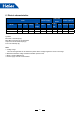
15. Capacity Cooling Outdoor Model MVAB009MV2AA MVAB012MV2AA MVAB018MV2AA Temp. Indoor Temp. 70.7°FDB 59°F WB 73.4°F DB 77°F DB 80.6°F DB 82.4°F DB 68°F WB 86°F DB 89.6°F DB 60.8°F WB 64.4°F WB 66.2°F WB 71.6°F WB 75.2°F WB °F DB CA SHC CA SHC CA SHC CA SHC CA SHC CA SHC CA SHC 68 8679 7071 9000 7071 9321 7071 9643 7071 9643 7393 9964 7071 10286 7071 72.
Heating Model MVAB009MV2AA MVAB012MV2AA MVAB018MV2AA SHC: sensible heat capacity Outdoor Temp. °F WB 5 14 23 32 36.5 42.8 43.7 50 54.5 59.9 5 14 23 32 36.5 42.8 43.7 50 54.5 59.9 5 14 23 32 36.5 42.8 43.7 50 54.5 59.9 Indoor Temp. (°F DB) 68.0 77.
Haier Commercial Air Condition Web: Http://www.haier.com Haier reserves the right to make change without any notice.