
Installation Manual


INSTALLATION
PAGE 7
ENGLISH SECTION A
(Heat Pump models only)
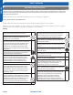
1.1
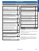
Step - 1.1
If attaching the supplied drain elbow to the outdoor unit,
do so prior to attaching the refrigerant lines and wiring.
Extension piping to attach to this tting is eld supplied.
Step1.2
Step 1.1
Step 1 - Installation of the Outdoor Unit
Attaching Drain Elbow to Outdoor Unit
1.2
Step - 1.2
Remove the cover plate of the outdoor unit to expose the
terminal block connections.
Electrical Connections for the Outdoor Unit
Step 1.3
Step 1.4
1.3
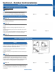
Step - 1.3
Connect the wiring for both the power source and indoor
wiring.
Wire the system according to applicable national / local
codes.
Verify that the wiring connections for the indoor unit match
wire for wire.
(1-1, 2-2, 3-3, Gnd-Gnd). Failure to wire the system correctly
may lead to improper operation or component damage.
1.4
Step - 1.4
Replace the cover plate.
Step 2.2Step 2.1
Outdoor unit
Indoor unit
A
B
Outdoor unit
Indoor unit
A
B
A
B
Outdoor unit
Indoor unit
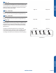
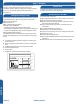
Oil trap
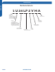
CAUTION
Max. Elevation: A Max.
= 100ft / 30m (24k / 36k)
In case the height of A is more than
15ft / 5m, an oil trap should be
installed every 16-23ft /5-7m
Max. Length: B Max
= 165ft / 50m (24k / 36k)
●
●
●
Illustration 4
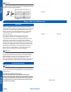
Step 2 - Connecting the Indoor Unit
Piping
The standard lineset length is 25ft. If the installation length is
different, adjust the refrigerant charge by 0.5oz/ft.for the
24k,36k,42k and 48k model. (Illustration 4)
Cut the lineset to length, are and attach the piping to the
outdoor unit valves.
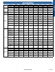
Torque the ttings to the specications shown in the torque
chart.
2.1
Step - 2.1
Refrigerant piping connections at the indoor unit are made
utilizing flare joints. Follow standard practices for creating
pipe flares. When cutting and reaming the tubing, use caution
to prevent dirt or debris from entering the tubing. Remember
to place the nut on the pipe before creating the flare.
2.2
Step - 2.2
To join the lineset piping together, directly align the piping
are to the tting on the other pipe, then slide the nut onto
the tting and tighten. Misalignment may result in a leaking
connection.
*See indoor section A, B, or C for electrical connections.
Section A - Outdoor Unit Installation