
Installation Manual


INSTALLATION
PAGE 8
ENGLISHSECTION A
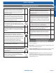
Hazard of Explosion! Never use an open flame to detect
refrigerant leaks.. Explosive conditions may occur. Use a leak
test solution or other approved methods for leak testing.
Failure to follow recommended safe leak test procedures
could result In death or serious injury or equipment or
property damage.
Use only dry nitrogen with a pressure regulator for
pressurizing unit. Do not use acetylene, oxygen or
compressed air or mixtures containing them for pressure
testing. Do not use mixtures of a hydrogen containing
refrigerant and air above atmospheric pressure for pressure
testing as they may become flammable and could result in
an explosion. Refrigerant used as a trace gas should only be
mixed with dry nitrogen for pressurizing units. Failure to
follow these recommendations could result in death or
serious injury or equipment or property damage.
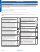
3.1
Step - 3.1
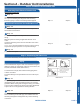
Using a tank of nitrogen with attached regulator, charge the
system with 150 PSIG of dry nitrogen. Use adapter AD-87
(field supplied) to connect to the service valve. Check for
leaks at the flare fittings using soap bubbles or other
detection methods. If a leak is detected, repair and recheck.
If no leaks are detected, proceed to evacuate the system.
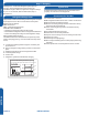
Step 3.1 Step 3.2
Illustration 5
Leak Test
System Evacuation
Step 3 - Leak Test and Evacuation
3.2
Step - 3.2
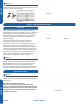
Attach a manifold gauge, micron gauge, and vacuum pump
to the suction line port using adapter AD-87 (eld supplied).
(Illustration 5)
Evacuate the system to 350 microns.
Close the vacuum pump valve and check the micron
gauge. If the gauge rises above 500 microns in 60 seconds,
evacuation is incomplete or there is a leak in the system. If
the gauge does not rise above 500 microns in 60 seconds,
evacuation is complete.
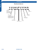
Step 2.3
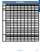
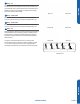
Table 1
Half union
Flarenut
Torque wrench
Spanner
Forced fasteningwithout carefulcentering may
damagethe threads and cause a leakageofgas.
Pipe Diameter(ǿ)Fastening torque
Liquid side6.35mm(1/4") 18N.m/13.3Ft.lbs
Liquid/Gas side9.52mm(3/8") 42 N.m/30.1Ft.lbs
Gasside12.7mm(1/2") 55N.m/40.6Ft.lbs
Gasside15.88mm(5/8") 60 N.m/44.3Ft.lbs
2.3
Step - 2.3
Two wrenches are required to join the are connections, one
standard wrench, and one torque wrench. See Table 1 for the
specic torque per piping diameter.