
Multi-Zone Technical Overview
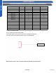

SW3-4 SW3-3 SW3-2 SW3-1
0 0 0 0
0 0 0 1
0 0 1 0
0 0 1 1
0 1 0 0
0 1 0 1
0 1 1 0
0 1 1 1
1 0 0 0
1 0 0 1
1 0 1 0
1 0 1 1
1 1 0 0
1 1 0 1
1 1 1 0
Wired controller address
Master indoor unit
Slave unit 1
Slave unit 2
Slave unit 3
Slave unit 4
Slave unit 5
Slave unit 6
Slave unit 7
Slave unit 8
Slave unit 9
Slave unit 10
Slave unit 11
Slave unit 12
Slave unit 13
Slave unit 14
Slave unit 15 1 1 1 1
for ON,“ 0” stands for OFF.
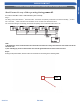
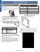
Step 3: setting the jumper CN22& CN23
The master indoor unit: Remain connected in CN22&CN23 (default)
The slave indoor unit: Remove all the jumpers in CN22&CN23.
CN22&CN23
Note:The above step 1, step 2, and step 3 must be operated in power off status.
ENGLISH
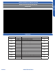
INDOOR SLIM DUCT
Connection method for one wired controller with multiple Slim Duct
TESTING PAGE 65