
Multi-Zone Technical Overview

OPERATIONS
PAGE 22
ENGLISH
On a call for heating, the indoor unit will send the room
temperature and set-point requirement to the outdoor unit
ECU via the data signal wire path. The data travels from the
indoor unit to the outdoor unit via the wire located on terminal
3. The indoor unit’s louver will open the indoor fan will remain
o.
EEV valves serving indoor circuits will step to a FULL OPEN
BYPASS position. Outdoor EEV valve serving outdoor coil
will step open to a pre-set metering position based upon the
temperature of the outdoor air.
The outdoor unit 4 way valve will be energized. Equalization
noise will be heard.
The outdoor fan motor will start.
The compressor will start in low RPS speed and gradually
speed up.
Indoor fan will begin to operate at slow speed and gradually
increase speed.
With the compressor operating, refrigerant will begin to ow
throughout the refrigeration circuit.
The operating frequency of the compressor will be displayed
on the Service Monitor Board Display.
When the compressor starts, the compressor will discharge
hot gas into the oil separator. Oil will be trapped in the
separator and returned to the suction inlet of the compressor
via the capillary tube assembly low pressure path.
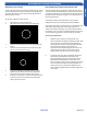
1
Temperature Sensor Td
The temperature of the compressor discharge hot gas will be
monitored by the Discharge Temperature Sensor. If the sensor
reads too hot or cool, the frequency/status of the operation will
potentially be altered.
The hot gas will leave the oil separator and enter the 4 way
valve. The 4 way valve will direct the hot gas to ALL of the
indoor coils.
Note: Any indoor unit that is in heating mode will have it’s louver
open and indoor fan running. Non-calling indoor units will receive hot
gas but their fans will remain on very low speed with the louver open.
When demand for heat increases, the indoor fan will speed up to
meet the increased demand.
2
Temperature Sensor Tc1 and
3
Indoor Heat Exchanger
Temperature Sensor
The temperature of Tc1 should now be hot. This will indicate
the 4 way valve is directing hot gas to the indoor coils. If it is not,
there is a problem with the 4 way valve. The ECU will detect the
temperature dierence and generate an Error Code.
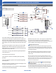
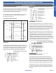
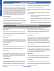
4U36HS1ERE 4U36MS2VHB
Comp-
ressor
Discharge temp.
sensor
Oil
separator
Capillary tube
High pressure
switch
4-way valve
Pipe sensor
Toci
Suction temp.
sensor
Low pressure
switch
Accumulator
Gas stop valve
Outdoor
heat
exchanger
temp.
sensor
FAN-OUT
Outdoor
ambient
temp.
sensor
Defrost
sensor
Distributor
Strainer
Check valve
Receiver
Liquid stop vavle
5/8
3/8
Strainer
Unit A liquid pipe temp. sensor
Indoor unit A
Strainer
Unit B liquid pipe temp. sensor
Indoor unit B
Strainer
Unit C liquid pipe temp. sensor
Indoor unit C
Strainer
Unit D liquid pipe temp. sensor
Indoor unit D
Unit A gas pipe temp. sensor
Unit B gas pipe temp. sensor
Unit C gas pipe temp. sensor
Unit D gas pipe temp. sensor
Indoor unit A
Indoor unit B
Indoor unit C
Indoor unit D
4-way valve coil:
OFF
ON
Refrigerant flow in cooling
Refrigerant flow in heating
FAN-IN
Indoor
ambient
temp.
sensor
Indoor
heat
exchanger
temp.
sensor
EEV A
B VEE
EEV C
EEV D
EEV O
φ2.7*φ1.0*55in
15
1
6
5
4
2
3
7
OUTDOOR UNIT SEQUENCE OF OPERATION
Heating Mode Sequence of Operation
valve