
Multi-Zone Technical Overview


TECHNICAL OVERVIEW
PAGE 15
ENGLISH
Technical - OverviewOUTDOOR UNIT TECHNICAL OVERVIEW
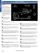
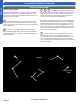
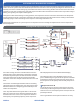
Module Circuit Board (MCB)
1
The Module Circuit Board generates 3 phase DC power
to operate the variable speed compressor. The compressor is
connected to the MCB via terminals CN-5. CN-6 and CN-7.
2
A Reactor Coil is connected to the MCB at terminals
CN-3 and CN-4. The Reactor Coil will lter out electrical noise
generated at high frequency operation. The ltering out of
electrical noise will prevent pin holes from being burned into
the compressor motor windings during high speed operation.
3
The MCB has 3 surface mounted LED indicators to aid
in diagnostics. The indicator LED colors are GREEN for Power/
Status, Red and Yellow for Diagnostic Codes.
4
The MCB generates heat that is transferred to a heat
sink located on the back of the board. The heat sink trans-
mits this heat to the outdoor air. A temperature sensor Tm is
attached to the inverter semi-conductor chip.
5
The temperature sensor is connected to the MCB via
terminal CN-11. If excessive heat is detected by this sensor,
the system will stop operation and generate an Error Code 38.
The RED Diagnostic LED indicator located on MCB will ash 14
times. When the sensor cools o, the system will re-start and
the diagnostic error codes will clear.
6
There is a communication cable connected to the MCV
via Plug CN-9. The wire from this plug goes to a connection on
the ECU board. If this plug is disconnected or loose, the RED
Diagnostic LED located on the MCB will ash 14 times and the
system will shut o on an Error Code 04.
Module Circuit Board (MCB)
1
2
3
4
5
6
Temperature Sensor
(located under board)
LEDs