
Multi-Zone Technical Overview


TECHNICAL OVERVIEW
PAGE 14
ENGLISH
TECHNICAL OVERVIEW
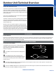
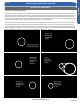
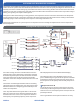
Electronic Control Unit Circuit Board (ECU)
Electronic Control Unit Circuit
Board (ECU)
The Electronic Control Unit
operates the outdoor fan motor,
crankcase heater, EEV stepper
motors and the 4-way valve.
This board also controls the
general operation of the system
and makes all of the diagnostic
decisions. The ECU is connected
via communication cables to
the Module Circuit Board, Power
Circuit Board and the Service
Monitor Board.
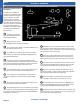
1
Voltage to operate the
ECU is provided by the PCB on
terminals ACN and ACL.
2
When this power is pres-
ent, the GREEN LED on the ECU should be lit.
3
The communication cables to the PCB and MCB boards
connect via Plugs CN6 and CN-9.
4
The SMB connects to plugs CN-23 and CN-8. When
these cables are connected to the SMB, the SMB digital dis-
play should be illuminated.
5
Plug CN-21 connects the data path between each
indoor unit and the outdoor unit ECU board. The connections
from this plug terminate at the Number 3 terminal at the volt-
age connection terminal strips for the indoor units.
6
The Outdoor Fan Motor is a DC voltage variable speed
type that connects to the ECU at terminal Plug CN-11.
7
The 4-Way Valve is energized by line voltage from a
connection via Plug CN-5. This valve is energized in HEAT
MODE.
8
The Crankcase Heater is energized via a connection at
terminals CON-9 and CON-8 on the ECU.
9
The EEV Stepper Motors are controlled via connections
at terminals CN-15 through CN-20. These EEV Stepper Motor
connections include the connection for the HEAT MODE EEV
located at the outdoor coil.
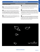
10
Each EEV has a set of temperature sensors that monitor
the temperature of the exiting liquid and entering vapor from
each evaporator circuit. These sensors are mounted in a group
near the center of the circuit board.
11
There are 6 system temperature sensors that monitor
refrigerant line temperature and outdoor air temperatures.
These sensors plug into the ECU via 2 Plugs CN-14 and CN-7.
12
The system has two refrigerant pressure switches, a Low
Pressure Switch and a High Pressure Switch. These switches
are connected to the ECU via Plugs CN-12 and CN-13.
13
There are 3 sets of DIP Switches located on the circuit
board. They are SW-7. (Factory Settings Only), SW-5 (Defrost
Adjustments) and SW-6 (Not Currently Used).
14
There are 4 surface mounted buttons located next to
SW-5 and SW-6. These buttons are for factory use only.
15
The ECU board has two LED Indicators, a GREEN power
indicator and a RED Diagnostic Indicator LED. When power is
present, both the GREEN and RED LED lights are lit.
16
A 15A 250V rated ceramic fuse is located on the ECU. This
fuse will open if excessive current occurs or if a power surge is
present. This fuse is eld replaceable.
7
9
1
5
6
3
4
8
14
11
13
16
15
10
12
2