
Multi-Zone Technical Overview

REFERENCES
PAGE 111
ENGLISH
FLOW CHARTSFLOW CHARTS
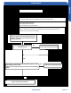
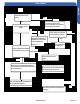
Caution: Be sure to turn power switch o before connecting or disconnecting the
connector, or parts may sustain damage.
YES
YES
NO
NO
1. Check whether terminals CN23 and CN24 and
terminals CN10 and CN 11 on the IPM module are
securely connected
Are they secure?
Replace the outdoor IPM module
Turn on the unit. Check that the voltage between pins 1 and 2 of
terminal CN23 is about 5VDC.
Check that the voltage between pins 2 and 3 of terminal CN23 is
15VDC
Replace the outdoor main board
Pull out and reinsert the terminals
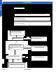
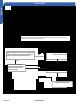
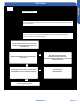
• The outdoor PCB is defective and will lead to a communication fault
• The IPM module is defective and will lead to a communication fault
•The outdoor PCB is defective
•The IPM Module is defective
• Communication wiring connections
LED1 ashes 4 times