
Multi-Zone Technical Overview

REFERENCES
PAGE 108
ENGLISH
FLOW CHARTS
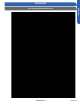
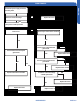
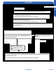
Caution: Be sure to turn power switch o before connecting or disconnecting the
connector, or parts may sustain damage.
Check to see that the terminal on the
outdoor main board is properly inserted.
Is it normal?
Reinsert the terminals.
NO
NO
NO
NO
YES
YES
Using the remote control, turn on
the unit in Cool Mode and check to
see if the motor is running.
Measure the voltage between
terminals 3 and 6 of the connector,
about 0-5VDC
Measure the voltage between terminals
1 and 3 of the fan motor connector on the
main board about 310VDC. Measure the
voltage between terminals 3 and 4 of the
connector about 15VDC. Measure the
voltage between terminals 5 and 3 of the
connector about 1-6VDC.
Is it normal?
Is it normal?
The motor of the outdoor unit is
damaged and needs to be replaced.
The main board of the outdoor
unit is damaged and needs to be
replaced.
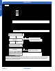
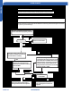
• DCfan motor protection due to the DC fan motor fault
• DC fan motor protection due to faulty PCB
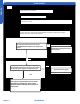
Caution: Be sure to turn power switch o before connecting or disconnecting the connector,
or parts may sustain damage.
LED 1 ashes 9 times
DC fan motor error is detected by checking the fan running condition
When the data of the EEPROM is in error or the EEPROM is damaged
DC fan motor protection due to a fault in the DC fan motor
YES