
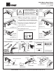
Installation Sheet

1-11/16"
(43mm)
3/8"
(10mm)
1-1/16"
(27mm)
7/16"
(11mm)
CONNECTING ROD
R
o
t
a
t
e
4
5
˚
2-1/4"
(57mm)
3"
(76mm)
1"
(25mm)
1"
(25mm)
2-5/16”*
(59mm)
Tube end toward lock stile.
Top of
Door
Frame
BEFORE INSTALLATION:
Turn backcheck selector valve (found on back side of closer) all the
way in (clockwise).
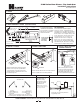
1. PARTS
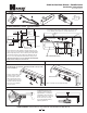
3. INSTALL CLOSER
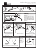
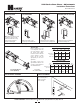
2. MARK AND DRILL HOLES (Right Hand Shown)
4. INSTALL CONNECTING ROD
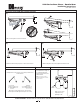
5. INSTALL MAIN ARM
Select hand of door. Fold template on the hinge edge of door line.
Fold or cut upper corner illustrated on template and align template
with the hinge edge of door. At the “Frame Stop Line” fold toward
you and attach template to door. Mark, prep and drill/tap 1/4"-20
holes for closer body and parallel arm bracket mounting screws.
*
Measured from frame Stop or pre-mounted jamb weatherstripping.
Install before measuring closer hole locations.
Use adjustable wrench to rotate
spindle 45˚ counterclockwise for
Right Hand Door or clockwise for
Left Hand Door. Place main arm on
spindle so that it is 45˚ or less from
the tube end of the closer body.
Secure main arm and spindle by
tightening spindle bolt.
Remove template and use
mounting screws to install
the closer body to the door
and the parallel arm bracket
to the frame soffit. Closer body
should be oriented so that the
tube of closer is toward the
lock stile of door.
Attach connecting rod to the parallel arm plate.
5100 Series Door Closer - Parallel Arm
Installation Instructions
Meets ANSI A156.4
3
4 holes for 1/4"-20
machine screws
4 holes for 1/4"-20
machine screws
An optional mounting plate is required where top rail is less than
5-1/2” (140mm). Plate requires 2” (51mm) minimum top rail.
HAGER COMPANIES 139 Victor Street, St. Louis, MO 63104 • (800) 325-9995 • Fax (800) 782-0149
7-7/8”
(200mm)
10”
(254mm)
11-1/2”
(292mm)
= 180˚
= 120˚
= 90˚
6-1/2”
(165mm)
8”
(203mm)
9-1/2”
(241mm)
= 180˚
= 120˚
= 90˚