
Installation Guide


27390031
2902 Electric Latch Retraction Controller
Installation Instructions
I-EA00002
INSTALLATION INSTRUCTIONS (cont)
The 2902 comes from the factory set up for use without fire alarm interface.
If the fire alarm is to be used with this controller, move the program jumper
PJ2 from between the middle post and the end post marked “FA DIS” (Fire
Alarm Disabled), to between the middle post and the end post marked “FA
EN” (Fire Alarm Enabled).
Note: The current drawn through fire alarm relay contacts will be 120mA @
24VDC
AUXILIARY POWER SOURCE OUTPUTS
Two constant, power limited auxiliary outputs are provided for powering
keypads, motion sensors, annunciator panels, electromagnetic door holders,
relays, LEDs, etc. Choose between auxiliary output #1 or auxiliary output #2.
• Auxiliary Output #1 Range: 26.7V - 28.0V, Nominal
• Auxiliary Output #2 Range: 12.6V - 16.5V, Nominal
Note: Both auxiliary outputs can be used at the same time for loads requiring
different voltages (for a combined maximum load current of 500mA).
However, do not tie the aux. output #2 ground (TB3, terminal 18) common to
the aux. output #1 ground (TB3, terminal 16). Both of these power sources
must be isolated from each other.
Caution: It is recommended to use output #2 with equipment that has
inputs rated for 12-24 volts, AC or DO. Check with the
manufacturer before connecting 24 VDC rated equipment across
output #1 to ensure the higher voltage will not cause any damage.
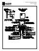
TYPICAL 2902 APPLICATION
A pair of doors is to be controlled by a computerized time system where it is
to be unlatched during business hours from 8:00 AM to 5:00 PM. During this
time, a handicapped wall switch located on the exterior and interior sides of
the door can be used to activate the automatic door operator.
After business hours, the computer locks the pair of doors and disables use
of the exterior handicapped wall switch. The inside wall switch remains
enabled after business hours and, when actuated, will momentarily retract
the latches and activate the automatic door operator. To gain entry, a card
reader located on the exterior side of the door momentarily retracts the
latches and simultaneously enables the outside wall switch to be activated by
the handicapped.
TROUBLESHOOTING
Before proceeding through the troubleshooting section, ensure that all device
latches are not binding against their corresponding strikes. A bound latch
can cause sluggish electric retraction or prevent retraction entirely.
Power Limited Outputs
All outputs to the 1426 are power limited. Depending on the output, if a short
circuit or an over load condition should occur, the output will either shut off
entirely or go into a safe current limiting state.
Important: The maximum rated load for all outputs combined is 2.0 AMPs,
including 250mA (max) for each auxiliary output.
The outputs to ELR DEVICE ONE (TB3, terminals 5 & 6) and ELR DEVICE
TWO (TB3, terminals 11 & 12) will completely shut down to 0 volts when a
short circuit across the output occurs or when the load exceeds 5 amps. To
reset the output, the short circuit or overload must first be located and
removed. Next, momentarily switch off the outputs by opening the contacts
across input terminals 1 & 2 or 7 &8, whichever is used. Before switching
outputs back on, ensure the load does not exceed the maximum current
ratings.
Both auxiliary outputs will go into a current limiting state when the load
exceeds approximately 2.0 amps or in the event of a short circuit. The
current is reduced to a safe level when either of these conditions occur. The
output voltage will automatically return to its normal level when the short
circuit or overload condition is removed and replaced by a load falling under
the maximum current rating.
Symptom:
Neither DEVICE ONE nor DEVICE TWO retracts after the control switch is
activated.
Possible Causes:
1. The power limited output to Device 1 or Device 2 (or both) may
have shut down. When this happens, the field wires that are run
to the exit device are probably shorted together against the
conduit, door frame or electric hinge.
2. If using the ELR device with polarized leads, the slow blow
4 amp fuse (Littelfuse #239.004) inside the exit device has blown.
The most likely cause would be reversed polarity of the exit device
red and black leads: RED = “+”; BLACK = “-”. (Refer to the wiring
diagram for proper connection.) Other possible causes may be
shorted wires in the solenoid assembly or a defective pulse
module.
3. An open connection in the field wiring between the power supply
and control switch used for activating latch retraction.
4. A defective control switch.
5. An open connection in the field wiring between the power supply
and exit device.
6. There may be no pulse. To check for pulses, prop the door open
and connect a voltmeter across the red and black leads coming
from the exit device (red lead is positive), or across the blue leads
if using the alternate non-polarized ELR device. Next,
connect a jumper wire across terminals 1 and 2 of TB3 to keep
DEVICE ONE in a continuous retracted state. If the voltmeter
measures between 30 and 40 VDC at the moment the jumper wire
was installed, but the latch did not budge, then no initial pulse was
generated. For the polarized ELR device, check for a
series of timed pulses that will occur approximately every six
seconds. (Make sure that the control rod is not positioned over
the reflective sensor on the pulse module when making this next
check.) Wait for about 20 seconds to see if the latch pulls in. If it
still does not respond, then it indicates the pulse module is
inoperative and the entire solenoid/module assembly must be
replaced.
REV 2
Page 2 of 4