
Installation Guide


27390031
2902 Electric Latch Retraction Controller
Installation Instructions
I-EA00002
INSTALLATION INSTRUCTIONS
For C-UL Listed applications, the unit shall be installed in accordance with
Part 1 of the Canadian Electrical Code. Transformer model BE31763001 by
Basler Electric and transformer model 2010028 by Galaxy Transformer and
Magnetics have been certified for UL and C-UL applications. Transformer
model A41-130-28A34 by EWC has been certified for UL applications only.
The 2902 enclosure should be securely fastened to the wall using the four
1/4 inch diameter mounting holes located in the back of the box. Position the
enclosure so that the transformer is located on the left-hand side. The 2902
must not be installed outdoors.
For the 120VAC power input, terminal block TB1 will accommodate up to 12
AWG wire (solid). Conduit must be used to provide an adequate earth
ground to the enclosure.
Note: The maximum input current is 750mA.
The 2902 is designed to be used with all Hager exit devices modified for
electric latch retraction. Use the chart below to determine the correct wire
gauge per given length of two-conductor cable that will be run from the 2902
to each exit device. Do not exceed the maximum length listed with each wire
gauge.
Wire Gauge Maximum Length of Two-Conductor Cable
16 AWG 40 feet
14 AWG 60 feet
12 AWG 100 feet
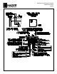
Up to two devices can be used with the 2902. If only one device is to be
used, wire to the “DEVICE ONE” location at TB3, terminals 5 and 6.
Note: When using the Hager electrified exit device with red and black leads,
be sure to observe polarity when connecting devices 1 and 2 to TB3. (Refer
to the wiring diagram located on the lid of the controller.)
STANDARD OPERATION
The 2902 is provided with two inputs. One is used for momentarily retracting
latches sequentially, followed by a signal to activate the automatic door
operator. The other is used with a maintain switch for sequentially retracting
latches only. This system will work for single door applications or on a pair of
doors using a device on one or both leaves.
Connect a momentary, normally open switch across terminals 1 and 2 of
terminal block TB3. Closing this switch momentarily will retract the latch of
DEVICE ONE and DEVICE TWO sequentially and follow with a dry contact
closure signal to the automatic door operator. Pot R2 is used to control the
length of time that the latch(es) remain retracted and the signal to the
automatic door operator remains active. Factory set to five seconds, pot R2
(located at the top of the p.c. board) can be field adjusted to the desired
delay time from 1 to 20 seconds. Turn the pot clockwise to increase the
delay time.
When using normally open contacts from a keypad or card reader with
built-in time delay, turn pot R2 fully counterclockwise to the minimum delay
time (approx. 0.5 sec.). A contact closure will activate latch retraction and
activate the automatic door operator. The device(s) will latch and the signal
to the automatic door operator will cancel within 0.5 second after the keypad
or card reader delay times out.
Note: Pot R4 is not used; do not adjust.
Connect a maintain switch across terminals 7 and 8 of terminal block TB3.
Closing this switch will sequentially retract the latch of DEVICE ONE and
DEVICE TWO, but will not activate the automatic door operator. Upon
opening the switch contacts, both devices will immediately latch (no delay
before latching).
Connect DEVICE ONE to TB3, terminals 5 and 6; positive red lead connects
to terminal 5. Polarity must be observed when using the ELR device with red
and black leads. Connect DEVICE TWO, if used, to TB3, terminals 11 and
12; positive red lead connects to terminal 11. (When connecting the
alternate ELR exit device with blue leads to terminals 5 and 6 or 11 and 12,
polarity is not observed.) The automatic door operator output, TB3, terminals
9 and 10, consists of normally open relay contacts that are field wired directly
to the “door activation” input of the automatic door operator.
Note: P.C. board program jumper PJ1 must always be left in place between
the middle post and the end post marked “S”.
1550C ELR SOLENOID ASSEMBLIES -
THEORY OF OPERATION
Hager provides two types of ELR (electric latch retraction) devices. One type
is designed to fit inside exit devices of narrow height and depth (1-1/4"). The
leads to these devices are polarized: Red lead = (+); Black Lead = (-). The
other type ELR device will fit into exit devices having a minimum height and
depth of 1-1/2". The leads to these devices are non-polarized and colored
blue.
ELR Device with Polarized Leads
This device contains a pulse module which delivers a pulse at 24VDC to a
high current coil inside the exit device every 6 seconds until the latch is finally
pulled back all the way. At this point, a control rod passes over a reflective
sensor and signals the module to stop pulsing. There is always an initial
pulse that occurs at the moment the system is activated. During the period
the system remains activated, output voltage is applied to a low current
secondary coil. This coil is responsible for holding the latch in the retracted
position until instructed to return to the “fail secure” position. (See Note 2 on
page 7.) The device contains a fuse to protect the ELR circuit in the event of
a reversed polarity wire connection.
ELR Device with Non-Polarized Leads
This device contains a powerful solenoid that performs both pulling and
holding functions. An initial high current pulse occurs each time output
voltage is applied to the device. After the pulse, the solenoid switches over
to a "holding" state by way of frequency modulation which reduces the
current to allow the solenoid to run at a cooler temperature. Because of its
non-polar design, the device contains no fuse.
OPERATION WITH FIRE ALARM
The 2902 can be wired to the fire alarm relay normally closed contacts.
When a fire alarm occurs, any door that is currently unlatched, whether by
momentary time delay or by maintained switch, will immediately latch secure.
During the time that the fire alarm is active, electronic control of the automatic
door opening system by wall switch, card reader, keypad, etc., is disabled.
The door then can only be opened manually.
REV 2
Page 1 of 4