
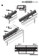
Installation Sheet


(&3
\\
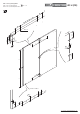
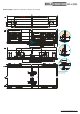
%INBAUBEISPIELE
\-OUNTINEXAMPLES\%XEMPLESDEMONTAGE
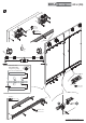
TH = KH – SH + 40
53
27
19
H – 257
19
19
8
2175
Ø 3,5 x 30
min. 60
80
Ø 4 x 25
40
Ø 4 x 20
Ø 3,5 x 16
Ø 4 x 16
max. 2288
KH max. 2400
H = KH – SH – 91
H
220
25 TB – 60 35
935
60
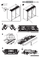
Typ S = 180
Typ M = 330
Typ L = 430
60
TB = KAM – 6 – (2xA)
2
X
20
W = X+4
Ø 3 x 3
50
63
Ø 8 x 11
H – 218
7
min. 65min. 65
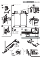
Ausrichtbeschlag
Door straightening system
Gabarit d'alignement
50
691 31,5
Ø 3 x 3
TB–W– 25
TB
KAM A MW
4 42
––
– 33
X =
47
12
142
H – 230
12
47
40
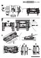
D
Bearbeitun
g
= rote Zahlen/Pre
p
aration = red numbers/Pré
p
aration = numéros en rou
g
e
min. 62
Ø 6,2 x 13,5
Ø 3,5 x 16
A
45°
Optimale Griffposition
Best handle position
Meilleure position pour la poignée
30
= =
TB = KAM – 6 – (2xA)
2
TB
29
47
20
Ø 4 x 30
Ø 4 x 20
20 20
80
29
47
20
Ø 3,5 x 30
Ø 4 x 20
20
20
80
19
2
24
531919
H
82
19
155
88
46,5
24
2
Ø 4 x 16
19 53
H
63
69,5
44
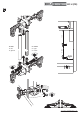
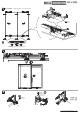
UPosition
Führungsschiene
Position
guide track
Position
rail de guidage
Einbaubeispiele/Mounting examples/Exemples de montage