DOC023.52.00022.
© HACH LANGE, 2005. All rights reserved. Printed in Germany.
DOC023.52.00022.Jul05 3700sc Digital Conductivity Sensor Opration Manual © HACH LANGE, 2005. All rights reserved. Printed in Germany.
Table of Contents Section 1 Specifications......................................................................................................................................... 5 Section 2 General Information ............................................................................................................................... 7 2.1 Safety Information ...............................................................................................................................................
Table of Contents Section 9 Contact ................................................................................................................................................ 31 Appendix A Modbus Register Information 4 ......................................................................................................
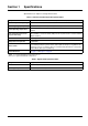
Section 1 Specifications Specifications are subject to change without notice. Table 1 Inductive Conductivity Probe Specifications Components Corrosion-resistant materials, fully-immersible probe with 6 m (20 ft) cable Conductivity Measuring Range 0.0 to 200.0; 0 to 2,000,000 microSiemens/cm Measuring Range (Temperature) –10 to 200.
Specifications 6
Section 2 General Information 2.1 Safety Information Please read this entire manual before unpacking, setting up, or operating this equipment. Pay attention to all danger and caution statements. Failure to do so could result in serious injury to the operator or damage to the equipment. To ensure that the protection provided by this equipment is not impaired, do not use or install this equipment in any manner other than that specified in this manual. 2.1.
General Information 2.2 General Sensor Information Optional equipment, such as mounting hardware for the probe, is supplied with instructions for all user installation tasks. Figure 1 Sanitary-style Sensor Figure 2 Convertible-style Sensor 2.3 The Digital Gateway The Digital Gateway was developed to provide a means to use existing analog sensors with the new digital controllers. The gateway contains all the necessary software and hardware to interface with the controller and output a digital signal.
Section 3 Installation DANGER Only qualified personnel should conduct the tasks described in this section of the manual. The 3700sc Digital Conductivity Sensor can be used with any sc controller. Refer to the controller manual for installation instructions. The sc sensor should be wired to the digital gateway before connecting it to the sc controller. The digital gateway is designed to provide a digital interface to the appropriate digital controller. Refer to section 3.1 for more information. 3.
Installation Figure 3 Wiring and Assembling the Digital Gateway 1. Digital gateway front 7. Nut, strain relief 2. O-ring 8. From sensor 3. Sensor wire connector 9. Insert wires into the connector according to Table 3. Use the included 2-mm screwdriver (Cat. No. 6134300) to secure connections. 4. Digital gateway back 10. Screw back of digital gateway onto front 5. Cable bushing 11. Push cable bushing and anti-rotation washer into back. 6. Anti-rotation washer 12.
Installation 3.2 Connecting Digital Gateway to the sc Controller The digital gateway should be wired to the sensor before connecting to the controller. 3.2.1 Attaching a sc Sensor with a Quick-connect Fitting The sensor cable is supplied with a keyed quick-connect fitting for easy attachment to the controller (see Figure 4: Attaching the Sensor using the Quick-connect Fitting). Retain the connector cap to seal the connector opening in case the sensor must be removed.
Installation Table 4 Wiring the Sensor at Terminal Block J5 Terminal Number Terminal Designation Wire Color 1 Data (+) Blue 2 Data (–) White 3 Service Request No Connection 4 +12 V dc Brown 5 Circuit Common Black 6 Shield Shield (grey wire in existing quick disconnect fitting) 3.3 Mounting the Digital Gateway The digital gateway is supplied with a mounting clip for mounting to a wall or other flat surface. Digital gateway dimensions are shown in Figure 6.
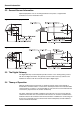
Installation 3.4 Installing the Sensor in the Sample Stream Locate the sensor as close a possible to the instrument. The convertible style sensor may be immersion mounted by threading it onto the end of a pipe of an appropriate length. It may also be mounted in any standard 2-in. NPT pipe tee, weldolet, or pipe saddle using the special union mount adapter. In addition, the sensor may be installed in a ball valve in a pressurized or non-pressurized process pipe/vessel.
Installation 14
Section 4 Operation 4.1 Using the sc Controller Before using the sensor in combination with an sc controller make yourself familiar with the operating mode of the controller. Refer to the controller user manual and learn how to use and navigate the menu functions. 4.2 Sensor Setup When a sensor is initially installed, the serial number of the sensor will be displayed as the sensor name. To change the sensor name refer to the following instructions: 1. Select the Main Menu. 2.
Operation 4.5 Sensor Setup Menu (continued) Resets all user-editable options to their factory-defaults. CONFIGURE EDIT NAME Enter a 10-digit name in any combination of symbols and alpha or numeric characters. SELECT MEASURE Choose from Conductivity, Concentration, TDS, or Salinity. If Concentration is selected, the option to configure the concentration settings is offered. Press the down arrow to Config Conc. Two concentration types are offered: Built-in and User Defined.
Operation 4.5 Sensor Setup Menu (continued) DIAG/TEST PROBE INFO Display the entered name of the sensor, the sensor serial number, the software version number, and the sensor driver version number. CAL DATA Displays the current offset correction and the date of the last calibration. SIGNALS SENSOR SIGNAL allows the user to set the sensor range and display the sensor ADC counts and TEMP ADC COUNTS shows raw data for temperature ADC counts. Comparable to A/D counts.
Operation 4.7 Calibration Calibration Methods When Measuring Conductivity: • Sample Cal Method: Enter the known conductivity value of the sample determined by laboratory analysis or a comparison reading. • Conductivity Cal Method: Enter the known conductivity value of calibration solution, and its linear % per °C and reference temperature values. • Zero Cal Method: Enter the zero value (in air).
Operation 4.7.2 Zero Cal A zero cal will mask interferences when mounting configurations are too close to objects (including the pipe when mounted in-line) in the sample or sample stream. 1. From the Main Menu, select SENSOR SETUP and confirm. 2. Highlight the appropriate sensor if more than one sensor is attached and confirm. 3. Select CALIBRATE and confirm. 4. Select ZERO. Select the available Output Mode (Active, Hold, or Transfer) from the list box and confirm. 5.
Operation 4.7.4 Cond Cal 1. From the Main Menu, select SENSOR SETUP and confirm. 2. Highlight the appropriate sensor if more than one sensor is attached and confirm. 3. Select CALIBRATE and confirm. 4. Select COND CAL. Select the available Output Mode (Active, Hold, or Transfer) from the list box and confirm. 5. Select SET REF TEMP and confirm. 6. Select SET SLOPE and confirm. 7. Move the probe to the solution and confirm to continue. 8. Confirm when stable. A CAL Complete will be displayed and confirm. 9.
Operation 4.8 Temperature Compensation The factory default for temperature compensation is linear with a 2.00% per °C slope and a 25 °C reference temperature. Change the type of sensor compensation by choosing Select Type. The available types are as follows: • NONE: No temperature compensation is applied. • LINEAR: Recommended for most applications. Choose Config Linear and confirm to access the menus for changing the slope or reference temperature. • NATURAL WATER: Not available for TDS.
Operation 5. Select SELECT TYPE. Select USER DEFINED or BUILT-IN and confirm. If USER DEFINED is selected: a. Select CONFIG TABLE and confirm. b. Confirm again to edit the points. If BUILT-IN is selected: a. Choose from the list of built-in tables. 4.8.3 Entering Values into the Configuring TDS Table If TDS has been selected in the Select Measure menu, the user may choose to enter values into the user defined table as follows: 1. From the Main Menu, select SENSOR SETUP and confirm. 2.
Section 5 Maintenance DANGER Only qualified personnel should conduct the tasks described in this section of the manual. DANGER Explosion hazard. Do not connect or disconnect equipment unless power has been switched off or the area is known to be non-hazardous. 5.1 Maintenance Schedule Maintenance Task 90 days Clean the sensor1 x Inspect sensor for damage x Calibrate Sensor (if required by regulatory agency) 1 Cleaning Per the schedule mandated by your regulatory agency.
Maintenance 24
Section 6 Troubleshooting 6.1 Error Codes When a sensor is experiencing an error condition, the sensor reading on the measurement screen will flash and all relays and analog outputs associated with this sensor will be held. The following conditions will cause the sensor reading to flash: • Sensor calibration • Loss of communication Highlight the Sensor Diag menu and confirm. Highlight Errors and confirm to determine the cause of the error. Errors are defined in Table 7.
Troubleshooting 26
Section 7 Replacement Parts and Accessories 7.
Replacement Parts and Accessories 28
Section 8 Warranty, liability and complaints HACH LANGE GmbH warrants that the product supplied is free of material and manufacturing defects and undertakes the obligation to repair or replace any defective parts at zero cost. The warranty period for instruments is 24 months. If a service contract is taken out within 6 months of purchase, the warranty period is extended to 60 months.
Warranty, liability and complaints 8.1 Compliance Information Hach Co. certifies this instrument was tested thoroughly, inspected and found to meet its published specifications when it was shipped from the factory. The Model sc100 Controller/sc1000 Controller with the Inductive Conductivity Sensor has been tested and is certified as indicated to the following instrumentation standards: Product Safety UL 61010A-1 (ETL Listing # 65454) CSA C22.2 No. 1010.1 (ETLc Certification # 65454) Certified by Hach Co.
Section 9 Contact HACH LANGE LTD Pacific Way Salford Manchester, M50 1DL Tel. +44 (0)161 8 72 14 87 Fax +44 (0)161 8 48 73 24 info@hach-lange.co.uk www.hach-lange.co.uk HACH LANGE HACH SAS 33, Rue du Ballon F-93165 Noisy Le Grand Tél. +33 (0)1 48 15 68 70 Fax +33 (0)1 48 15 80 00 info@hach-lange.fr www.hach-lange.fr DR. BRUNO LANGE GES. MBH Industriestraße 12 A-3200 Obergrafendorf Tel. +43 (0) 2747 - 74 12 Fax +43 (0) 2747 - 42 18 info@hach-lange.at www.hach-lange.de DR.
Appendix A Modbus Register Information Table 9 Sensor Modbus Registers Group Name Tag Name Register # Data Type Length R/W Tags SensorMeasTag 40001 Measurements DOMeas Tags Description Integer 1 R Sensor Measurement Tag 40002 Float 2 R DO Measurement TempMeasTag 40004 Integer 1 R Temperature Measurement Tag Measurements TempDegCMeas 40005 Float 2 R Temperature Measurement Configuration SensorName 40007 String 6 R/W Sensor Name Tags FuncCode 40013 Integer 1 R/W
Modbus Register Information Table 9 Sensor Modbus Registers (continued) Group Name Tag Name Register # Data Type Measurements TempDegCMeas 40005 Configuration SensorName 40007 String 6 R/W Sensor Name Tags FuncCode 40013 Integer 1 R/W Function Code tag Tags NextState 40014 Integer 1 R/W Next State Tag Configuration TempUnits 40015 Integer 1 R/W Temperature Units—C or F Configuration Filter 40016 Integer 1 R/W Sensor Filter Configuration TempElementType 40017 Integ
Modbus Register Information 34
Index C Calibration ..............................................................17, 18 One Point ............................................................... 20 Cleaning Controller ............................................................... 23 Sensor.................................................................... 23 Compliance Information................................................ 31 Configuring System ................................................................... 15 D Display......
Index 36