
Instruction Manual

41
Additional information for series 34xx sensors
A.4 Digital gateway
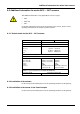
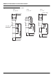
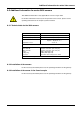
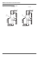
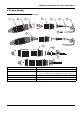
Figure 17: Connection digital gateway / 83xx
1. Front of housing 7. Union nut
2. O-ring 8. From the sensor
3. Sensor wire connections 9. Cable assignment as per
Table 12: "Cable assignment, digital gateway / 83xx" on page 44.
4. Rear of housing 10. Bolt together the housing for the digital gateway.
5. Cable sleeve 11. Slide back the cable sleeve and the washer.
6. Washer 12. Tighten the union nut.
1
2
3
4
5
GRY
PNK
WHT
BRN
1
6
5432
9
10
11
12
7
8
1
2
3
4
5
PINK
WHITE
GREY
BROWN