DOC023.52.03221.
© HACH LANGE GmbH, 2007. All rights reserved. Printed in Germany.
DOC023.52.03221.May07 1720E Low Range Turbidimeter USER MANUAL May 2007, Edition 7 © HACH LANGE GmbH, 2007. All rights reserved. Printed in Germany.
Table of Contents Section 1 Specifications......................................................................................................................................... 3 Section 2 General Information ............................................................................................................................... 5 2.1 Safety Information ...............................................................................................................................................
Table of Contents Section 8 Replacement Parts and Accessories.................................................................................................. 33 8.1 Replacement Items............................................................................................................................................ 33 8.2 Optional Accessories......................................................................................................................................... 33 8.
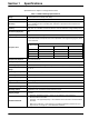
Section 1 Specifications Specifications are subject to change without notice. Table 1 1720E Low Range Specifications Range 0–100 nephelometric turbidity units (NTU) Measurement Units mg/L, NTU, TE/F, FTU, Degree Accuracy1 ± 2% of reading or ± 0.02 NTU (whichever is greater) from 0 to 40 NTU; ± 5% of reading from 40 to 100 NTU (when calibration is performed at 20.0 NTU with the offset turned off). Linearity1 Better than 1% 0–40 NTU on formazin.
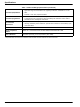
Specifications Table 1 1720E Low Range Specifications (continued) 1. StablCal® (stabilized formazin) – recommended for verification in the appropriate application range of measurement. For regulatory verification, standards of 0.1 to 50 NTU. 2. Formazin – fresh user-prepared standard 1. ICE-PIC™ Verification Module with factory-set values of 20.0 or 1.0 ±25%.
Section 2 General Information 2.1 Safety Information Please read this entire manual before unpacking, setting up, or operating this equipment. Pay attention to all danger and caution statements. Failure to do so could result in serious injury to the operator or damage to the equipment. To ensure that the protection provided by this equipment is not impaired, do not use or install this equipment in any manner other than that specified in this manual. 2.1.
General Information 2.1.3 General Product Information The 1720E Turbidimeter is a continuous-reading nephelometric turbidimeter designed for low-range turbidity monitoring. This process turbidimeter is capable of measuring turbidity from 0.001 to 100.0 NTU. Calibration is based on formazin, the primary turbidity reference standard adopted by the APHA Standard Methods for the Examination of Water and Wastewater and the U.S.
General Information 2.2 Theory of Operation The 1720E Turbidimeter measures turbidity by directing a strong beam of collimated light from the sensor head assembly down into the sample in the turbidimeter body. Light scattered at 90° relative to the center line of incident light by suspended particles in the sample is detected by the submerged photocell (Figure 1). The amount of light scattered is proportional to the turbidity of the sample.
General Information 8
Section 3 Installation DANGER Only qualified personnel should conduct the tasks described in this section of the manual. The 1720E/sc100 product configuration is not intended for installation in hazardous locations. 3.1 Connecting/Wiring the Sensor to the sc100 Controller 3.1.1 Attaching a sc Sensor with a Quick-connect Fitting The sensor cable is supplied with a keyed quick-connect fitting for easy attachment to the controller, see Figure 2.
Installation 3.1.2 Hard-wiring a sc Sensor to the sc100 Controller 1. Disconnect power to the controller if powered. 2. Open the controller cover. 3. Disconnect and remove the existing wires between the quick-connect and terminal strip J5, see Figure 3. 4. Remove the quick-connect fitting and wires and install the threaded plug on the opening to maintain the environmental rating. 5. Cut the connector from the sensor cable. 6. Strip the insulation on the cable back 1-inch.
Installation Figure 3 Hard-wiring the Sensor J1 J3 S1 U9 ANALOG OUTPUTS J4 J5 PCB CONNECTOR NETWORK INTERFACE CARD NC COM NO RELAY 1 NC COM NO RELAY 2 1 2 3 4 5 6 + DATA 1 2 3 4 5 + OUT 2 – DATA SERVICE REQUEST +V GND F1 U5 F2 PROBES J2 – OUT 2 SHIELD/CHASSIS GND + OUT 1 – OUT 1 NC COM NO RELAY 3 DANGER - EXPLOSION HAZARD DO NOT DISCONNECT WHILE CIRCUIT IS LIVE UNLESS AREA IS KNOWN TO BE NON-HAZARDOUS.
Installation Figure 4 12 1720E Dimensions
Installation 3.3.1 Mounting the Turbidimeter Body Locate the turbidimeter as close to the sampling point as possible. A shorter distance for the sample to travel results in a faster response time. Clean the turbidimeter body and bubble trap before installation using the instructions supplied in section 6.4.2 on page 26. Slotted mounting brackets are integral parts of the turbidimeter body.
Installation Figure 5 Sampling Techniques 1 3 2 4 5 6 7 8 1. Sample Flow 4. Sediment (Typical) 7. Good 2. Sampling Line to Sensor 5. Poor 8. Best 3. Air (Typical) 6. Poor 3.5 Sample Connections Sample inlet and drain connections are made on the turbidimeter body. The sample inlet fitting installed in the body is a ¼-inch NPT x ¼-inch compression fitting.
Section 4 System Startup 4.1 General Operation Plug the sensor into the unpowered controller by aligning the orientation tab on the cable connector with the channel in the controller connector. Push in and turn to secure the connection. Tug gently to check the connection. After all plumbing and electrical connections have been completed and checked, place the head on the body and supply power to the system.
System Startup 16
Section 5 Operation 5.1 Sensor Setup When a sensor is initially installed, the serial number of the sensor will be displayed as the sensor name. To change the sensor name refer to the following instructions: 1. Select Main Menu. 2. From the Main Menu, select SENSOR SETUP and confirm. 3. Highlight the appropriate sensor if more than one sensor is attached and confirm. 4. Select CONFIGURE and confirm. 5. Select EDIT NAME and edit the name. Confirm or cancel to return to the Sensor Setup menu. 5.
Operation 5.4 Sensor Setup Menu SELECT SENSOR (if more than one sensor is attached) CALIBRATE USER PREPD CAL Calibration using 4000 NTU stock solution diluted to 20.00 NTU formazin. STABLCAL CAL Calibration using 20 NTU StablCal Stabilized Formazin Standard VERIFICATION Perform a verification, set the pass/fail criteria, and view the verification history. 0 ELECTRONICS Zero electronics CAL HISTORY View the last 12 entered calibrations. Confirm to move to the next history entry. See section 5.
Operation • Stop sample flow, drain, and clean the turbidimeter body before beginning the calibration procedure. • Always clean the photocell window per the instructions in section 6.4.1 on page 26. Rinse the photocell with deionized water and dry with a soft, lint-free cloth before calibrating. • Always clean the turbidimeter body or calibration cylinder per the instructions in section 6.4.2 on page 26. Rinse with deionized water before calibrating.
Operation 9. Stop the sample flow. Drain and clean the body and bubble trap. Fill the cylinder with 1 L deionized water. Replace the head and confirm. Important Note: Carefully pour the DI water in such a way that minimizes any bubble formation that would result in a false, high reading. 10. The measured reading (based on a gain of 1.0) is displayed. Confirm. 11. Enter the standard turbidity value of the user prepared standard and confirm. 12. Drain the cylinder.
Operation serial number). As long as the verification exists within the verification history, the expected value will be retained. Otherwise, the expected value will be the nominal value associated with the dry verification device. 10. Select the VERIFICATION type (begin at step 5 in section 5.5.3.1 on page 21 for dry verification or section 5.5.3.2 on page 21 for wet verification) or enter initials to complete calibration. 11. Return the sensor to measure mode and confirm. 5.5.
Operation 4. Select PERFORM TEST and confirm. Select the available Output Mode (Active, Hold, or Transfer) from the list box and confirm. 5. Select WET for the verification type and confirm. 6. Enter the Std Turbidity and confirm. 7. Drain and clean the sensor body and confirm. 8. Pour the standard into cylinder. Replace the head and confirm. 9. The reading will be displayed. Confirm to accept the verification. 10. Return the sensor to measure mode and confirm. 5.
Operation 5.7.1 Setting the Offset Follow the steps below to enter an offset: Note: The data log for this channel will be erased if the offset is changed to anything other than zero. 1. From the Main Menu select SENSOR SETUP and confirm. 2. Select 1720E and confirm. 3. Select CONFIGURE and confirm. Note: Offset is not used during calibration. During calibration the offset is zero. 4. Move the pointer to OFFSET and confirm. 5. The display will show an Offset screen. Use the arrow keys to enter the offset.
Operation 24
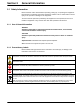
Section 6 Maintenance DANGER Only qualified personnel should conduct the tasks described in this section of the manual. 6.1 Maintenance Schedule Maintenance Task Frequency Clean the sensor Before each calibration and as needed. Depends on sample characteristics. Calibrate Sensor (as required by regulatory agency) Per agency-dictated schedule. Scheduled periodic maintenance requirements of the 1720E are minimal and include calibration and cleaning of the photocell window, bubble trap, and body.
Maintenance 6.4 Cleaning 6.4.1 Cleaning the Photocell Window Occasional cleaning of the photocell window is required. The frequency will depend on the nature and concentration of dissolved and suspended solids in the sample. Biological activity is a primary factor in mineral scale deposit on the window and the amount differs with sample temperature. In general, more growth will occur in warm temperatures and less in cold. Note: Do not disassemble the photocell assembly. It contains liquid.
Maintenance 4. Replace the bubble trap cover and head assembly on the top of the body. 5. Restore sample flow to the instrument. 6. Calibrate the instrument using one of the methods in section 5.5 on page 18. If the above cleaning procedures have been performed and the turbidimeter readings are still noisy, the bottom plate and gasket may need to be removed and cleaned. Carefully perform the following procedure to ensure the turbidimeter body integrity is maintained. 1.
Maintenance 3. After the bulb has cooled, remove as follows: a. Wear cotton gloves to protect your hands and to avoid fingerprints on the bulb. b. Grasp the bulb. c. Twist the bulb in a counterclockwise direction, pulling out slightly, until it is released from the housing. d. Pull the lamp leads and connector through the hole in the lamp housing. Do not touch the new bulb with bare hands. Etched glass and reduced lamp life will result.
Section 7 Troubleshooting 7.1 Error Codes When a sensor is experiencing an error condition, the sensor reading on the measurement screen will flash and all relays and analog outputs associated with the sensor will be held. Highlight the Probe Diag menu and press ENTER. Highlight Errors and press ENTER to determine the case of the error. Errors are defined in Table 3. Table 3 Error Codes Displayed Error Definition A/D Fail Failed A/D converter. Call the Service Department.
Troubleshooting Table 5 presents sensor warnings displayed in the Event Log, possible causes, and corrective actions. Table 5 General Troubleshooting Sensor Warning Bad Lamp Low Signal Bad System Voltage A/D Converter Timeout High Dark Counts Possible Cause Corrective Action Lamp burned out Replace the lamp. See section 6.4.3 on page 27.
Troubleshooting Table 6 Additional Malfunctions Not Recorded in the Event Log (continued) Symptom Possible Cause Corrective Action High Readings Deionized water turbidity is greater than 0.5 NTU Clean the instrument. Access Calibration History for turbidity value of ultra-filtered water. Verify the flow is between 200–750 mL/min. Recalibrate the instrument. 7.3 Event Codes Event codes are not displayed on controller and must be downloaded from the event log to be viewed.
Troubleshooting 32
Section 8 Replacement Parts and Accessories 8.1 Replacement Items Description QTY Catalog Number Lamp Assembly each 18950-00 Instruction Manual, 1720E Turbidimeter System, English each 60100-18 Description QTY Catalog Number Cable, sensor extension, 7.7 m (25 ft) each 57960-00 Cap, Connector Receptacle each 52100-00 1L 272-56 Drain plug for the 1720E body each 44116-00 Filter, 0.45 µm, to produce ultra-filtered water for cleaning and calibration each 26705-00 Filter, 0.
Replacement Parts and Accessories 8.3 Calibration and Verification Standards and Accessories Description Calibration Cylinder QTY Catalog Number each 44153-00 500 mL 2461-49 ICE-PIC™ Module, 1 NTU 1 each 52215-00 ICE-PIC™ Module, 20 NTU 1 each 52250-00 StablCal® Stabilized Formazin Standard, 1 NTU 1L 26598-53 StablCal® Stabilized Formazin Standard, 20 NTU 1L 26601-53 StablCal® Stabilized Formazin Standard, <0.
Section 9 Contact HACH LANGE GMBH Willstätterstraße 11 D-40549 Düsseldorf Tel. +49 (0)2 11 52 88-0 Fax +49 (0)2 11 52 88-143 info@hach-lange.de www.hach-lange.com HACH LANGE LTD Pacific Way Salford GB-Manchester, M50 1DL Tel. +44 (0)161 872 14 87 Fax +44 (0)161 848 73 24 info@hach-lange.co.uk www.hach-lange.co.uk HACH LANGE LTD Unit 1, Chestnut Road Western Industrial Estate IRL-Dublin 12 Tel. +353(0)1 46 02 5 22 Fax +353(0)1 4 50 93 37 info@hach-lange.ie www.hach-lange.ie DR. BRUNO LANGE GES.
Contact HACH LANGE 8, Kr. Sarafov str. BG-1164 Sofia Tel. +359 (0)2 963 44 54 Fax +359 (0)2 866 04 47 info@hach-lange.bg www.hach-lange.bg HACH LANGE SU ANALİZ SİSTEMLERİ LTD.ŞTİ. Hilal Mah. 75. Sokak Arman Plaza No: 9/A TR-06550 Çankaya/ANKARA Tel. +90 (0)312 440 98 98 Fax +90 (0)312 442 11 01 bilgi@hach-lange.com.tr www.hach-lange.com.tr ΗΑCH LANGE E.Π.Ε. Αυλίδος 27 GR-115 27 Αθήνα Τηλ. +30 210 7777038 Fax +30 210 7777976 info@hach-lange.gr www.hach-lange.gr HACH LANGE E.P.E.
Section 10 Warranty and liability The manufacturer warrants that the product supplied is free of material and manufacturing defects and undertakes the obligation to repair or replace any defective parts at zero cost. The warranty period for instruments is 24 months. If a service contract is taken out within 6 months of purchase, the warranty period is extended to 60 months.
Warranty and liability 38
Section 11 Compliance Information Hach Co. certifies this instrument was tested thoroughly, inspected and found to meet its published specifications when it was shipped from the factory. The Model sc100/sc1000 with 1720E Sensor has been tested and is certified as indicated to the following instrumentation standards: Product Safety UL 61010A-1 (ETL Listing # 65454) CSA C22.2 No. 1010.1 (ETLc Certification # 65454) Certified by Hach Co. to EN 61010-1 Amds.
Compliance Information Canadian Interference-causing Equipment Regulation, IECS-003, Class A Supporting test records by Hewlett Packard, Fort Collins, Colorado Hardware Test Center (A2LA # 0905-01) and certified compliance by Hach Company. This Class A digital apparatus meets all requirements of the Canadian InterferenceCausing Equipment Regulations. Cet appareil numÈrique de la classe A respecte toutes les exigences du RËglement sur le matÈriel brouilleur du Canada.
Appendix A Modbus Register Information Table 8 Sensor Modbus Registers Tag Name Register # Data Type Length R/W Units (U) Range Cal Gain 40013 float 2 R none 0.5 to 2.
Modbus Register Information 42
Index Numerics P 90 Degree Detector ................................................... 7 Photocell Window .................................................... 26 Power Requirements ................................................. 3 A Accuracy .................................................................... 3 R B Range ........................................................................ 3 Response Time .......................................................... 3 Bubble trap ................
Index 44