
Operating Instructions and Installation Instructions

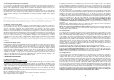
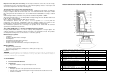
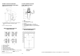

EXAMPLE: PROTECTIVE BARRIER
FOR THE HEATING DEVICE AND SMOKE
FLUE (dimensions in mm)
Printed: TISKÁRNA ŘEHÁK Česká Lípa, Czech Republic, Tel.: +420 487 853 897
PASSAGE THROUGH THE FIRE
PROOF SMOKE FLUE WALL
(dimensions in mm)
1 – Wall
2 – Smoke flue system
3 – Cover (fireproof, non-metal)
4 – Rosette
5 – Protective pipe (fireproof, non-metal)
6 – Insulating filler I (fireproof, e.g. glass fibre)
7 – Insulating filler II (fireproof, e.g. filler designed
for stoves)
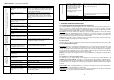
1 – Ceramic (metal) insert
2 – Metal chimney body
3 – Chimney walling
4 – Metal smoke flue system
5 – Hole in the chimney body
6 – Sealed branch to the chimney body
7 – Shim, fixed to the body with metal tapes
8 – Dilatation gap between the brick shape and the chimney walling
CORRECT – see. c, d WRONG – see a, b
Comment
s on ČSN 73 4201 :
2008
CLEARANCE BETWEEN THE INSERT
AND THE SURROUNDINGS
SMOKE FLUE CONNECTION IN THE
CHIMNEY BODY HOLE
Minimum clearances
A>=800 mm
B>=400 mm
1 – Protective barrier for the heating device and smoke flue
protecting surrounding constructions against
heat
2 – Hole for feeding and ashpan
19