
Operation Manual
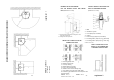
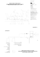


General scheme: heating system 1
Protection against overheat in case of electric power failure
with use of a cooling exchanger (loop).
supplement 4
supplement 3
Inlet and reverse piping (Warm water)
Cooling exchanger piping
Cable CYKY 3Cx1,5
Flow direction
Legend:
1. Warm water exchanger
2. .Circulating pump
3. .Expansion tank
4. Heating body
5. .Discharge valve
6. .Safety valve
7. Thermostatic valve ESBE, warm water 25 –
60 °C
8. Ball cock
9. .Closing filter
10. .Pressure gauge
11. Deaerating valve
12. Waste
13. .Cooling exchanger (look)
14. Safety warm water valve
General scheme: heating system 2
Combined heating system : Electric boiler + fireplace
stove , branches A and B, backup UPS 300.
Separating valves – heat circuits I- II:
Designed for separation of the heat circuits A
and B.
Heat circuit B: A part of the heat circuit.
Only for the fireplace stove.
Heat circuit A: General heat circuit. Both
devices in operation at a time.
Instal a thermoregulating valve , e.g .ESBE
TV25, opening temperature 60oC. When this
temperature is reached, the valve opens , and
the liquid from the heat system B (or A+B) is
let in the fireplace stove circuit (3-1).
The
inlets 1 and 3 of the valve are open – to
provide minimum temperature required for the
reverse water.
The recommended temperature gradient is 75-
60 °C. To provide this, the following
conditions must be met:
B – Connection to the parts of the system
A – connection to the general heating system
12
Backup UPS 300
11. Thermostat
10. Deaerating valve
9
Electric boiler
8. Pressure gauge
7. Ball cock
6. Closing valve
5. Safety valve
4. Thermoregulation valve , e.g. ESBE TV25
3
Expansion vessel
2. Circulating pump
1. Fireplace stove and exchanger
LEGEND:
Warm water inlet piping
Warm water reverse piping
A – A)Warm water output
B
–
B)
Reverse water input
C – Input of cooling water in the cooling exchanger (loop)
D – Cooling water output (into the sewage system)
The cooling exchanger (look) , the protection against
overheat (13), must not be used for other purposes than as
designed!
Connection to cold water system
24
25