
Information


7
Design and specifi cations are subject to change without notice. Ask factory for technical specifi cations before purchase and/or use.
Whenever a doubt about safety arises from this product, please contact us immediately for technical consultation.
Gold Capacitors Technical Guide
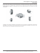
Principles and Operation of Gold Capacitors
The resistance values can increase or decrease
depending on the distance between the current
collectors, speed or ions, contact resistance between
the activated carbons, etc. The equivalent circuit of an
electric double layer capacitor is shown by the parallel
R-C combinations (Fig.7).
R
1
, R
2
and R
n
are the internal resistance of the
activated carbons. C
1
, C
2
and C
n
are the electrostatic
capacitance of the activated carbons having
resistances R
1
, R
2
and R
n
.
If voltage(V) is applied to the equivalent circuit shown
in Fig.8, the charging current(i) will vary according to
Therefore, the current (i) within the capacitor can be regarded as
the sum (Σi
n
) of the currents fl owing through each of the small
capacitors. It also can be seen that if the CxR value is small, the
charging time will be short. Conversely, if the CxR value is large, the
charging time will be long. The sum of the small capacitor charging
currents is shown in Fig.10.
It should be noted that if the charging time is limited to only
several minutes, or the charging source is current limited, the
Gold Capacitor may not be suffi ciently charged to provide the
required back-up energy for the time needed. If the capacitor is not
suffi ciently charged and is called upon to discharge its energy into
a load, the discharge current will fl ow from a high voltage level to
a low voltage level thereby causing a low terminal voltage. These
conditions are shown in Fig.11, 12.
If one considers the equivalent circuit of the electric double layer capacitor (Fig.8)
as having many small capacitors (C
n
) with various internal resistance (R
n
), then the
current that fl ows through an individual capacitor can be represented by Equation 2.
(1)
(2)
Equation 1 shown below. It should be noted that the charging current(i) decreases as charging time increases and is
shown in Fig.9. The charging current given by equation (1) will graphically be shown as a straight line. However, the
actual charging current curve is exponential.