
Operation Manual


18
EXAFEED 4L
EN
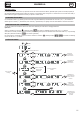
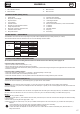
MODE SELECTION ON THE WELDING MACHINE
On the machine, press the button several times until the LED light switches on below the symbol .
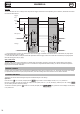
Both display show and the knobs are inactive, all controls are now operated from the wire feeder’s interface (FIG-2).
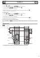
WELDING PARAMETERS SETTINGS
1. Setting the welding voltage :
Adjust the welding voltage using the main knob depending on the work to be carried out. The voltage setpoint is indicated on the left side
display.
2. Setting the wire speed :
Adjust the wire speed using the right knob depending on the work to be carried out. The speed setpoint is indicated on the right side display.
3. Setting the inductance :
While pressing the button , turn the knob , the index shows a value from -9 à +9. The lower the inductance level, the harder and more
guiding the arc. The higher the inductance and the softer the arc with little splatter.
ACCESS TO ADVANCED SETTINGS
Refer to the chapter « menu access » for more details regarding welding parameters.
(1)
« SPot », welding duration (in seconds) in Spot / Delay mode.
(1)
« DeLaY », stop duration (in seconds) in Spot / Delay mode
« PrEgaz », Pre gas, duration (in seconds) of the gas ow between the pressing of the trigger and the start of the wire feeding.
« I Start », starting current (relative scale from -5 to +5), the default value is 0
« Creep Speed », wire creep speed (percentage) before arc ignition
(2)
« Hot Start », Activation / deactivation of hotstart settings (On/Off)
(3)
« Creep Voltage », voltage (percentage) at arc ignition
(3)
« HotStart Speed », speed (percentage) during Hotstart
(3)
« HotStart Voltage », voltage (percentage) during Hotstart
(3)
« HotStart time », duration (in seconds) of the Hotstart phase
(4)
« Crater Filler », activation / deactivation of crater ller mode (On/off)
(5)
« Crater Filler Speed », speed (percentage) during crater lling
(5)
« Crater Filler Voltage », voltage (percentage) during crater lling phase
(5)
« downSlope time », duration (in seconds) of the downslope from main welding current to crater lling phase
(5)
« Crater Filler time », duration (seconds) of the crater lling phase
« burnback », energy required to draw back the wire (relative scale from -5 à +5), the default value is 0
« Post Gaz », duration (in seconds) of the gas ow after the welding stops
(1)
:
these settings are only available in Spot / Delay mode.
(2)
:
the Hotstart settings are only available in Spot / Delay mode.
(3)
:
these settings are only visible if H.S. is set to « On ».
(4)
:
the CraterFiller settings are only available in Spot / Delay mode.
(5)
:
these settings are only visible if C.F. is set to « On ».
DISPLAY CURRENT/VOLTAGE DURING WELDING
During welding, the machine measures and displays the welding current and voltage. After the weld, the average current and voltage values are
displayed during 30 seconds, as soon as a knob or a button is pressed, the welding parameters are displayed.
Depending on the operation (short-circuit, globular or spray-arc), the average voltage can slightly differ from the setpoint voltage.
SAVE AND LOAD WELDING SETTINGSS
The current settings are automatically saved and loaded at start up.
On top of the current settings, it is also possible to save and load settings per each mode.
There are 50 memory slots
The saved settings include :
- voltage, wire speed and inductance,
- advanced settings.
- 2T / 4T / SPOT DELAY mode