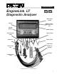
OPERATOR’S MANUAL EngineLink LT ™ Diagnostic Analyzer 55 BNC 1 Sync Output I/R Port BNC 2 PrimarySecondary Output Control Buttons Backlit Display Auxiliary Volts Leads Spark Pickup Spark Can Power Leads Amp Probe Coil Primary Clip Spark Can Ground KV Clips Primary Amps Probe © Copyright 2005, GxT, Inc.
Contents Specifications.........................................................................................................................................3 Connecting to a DIS Car........................................................................................................................4 Connecting to a Distributor Car............................................................................................................5 Connecting to a No Coil Minus...................................
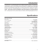
Introduction The EngineLink™ is a professional grade tool for diagnosing automotive ignition, fuel injection, and electrical systems. Test DIS and Distributor engines. Diagnose problems with ignition, starting/charging and fuel-delivery systems, as well as computer sensors and drivers. Our AutoSort feature automatically determines coil and plug polarity on DIS engines.
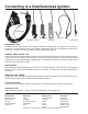
Connecting to a Distributorless Ignition Sparkwire Clips Spark Pickup Primary Amps Pickup Power Leads Amp Probe Auxiliary Lead SPARKWIRE CLIPS The EngineLink™ automatically sorts negative and positive firing plugs, and figures out coil pairings. Connect the center Sparkwire Clip to #1 Cylinder, and connect the rest of the Sparkwire Clips to any cylinder in any order. Connect the ground lead to a good engine ground.
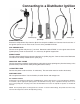
Connecting to a Distributor Ignition Sparkwire Clip Auxiliary Lead Coil Primary Clip Spark Pickup Amp Probe Power Leads SPARKWIRE CLIPS Disconnect all Sparkwire Clips from the Spark Can except the middle lead. Connect it to the coil wire. If the ignition system uses an internal coil, use one of the provided KV Plates. COIL PRIMARY CLIP Connect to the ignition coil primary (-) terminal. Sometime labeled “TACH”, it is the signal source for the ignition primary circuit measurements.
Connecting to a No Coil Minus Ignition Sparkwire Clip Auxiliary Lead Coil Primary Clip Spark Pickup Amp Probe Power Leads SPARKWIRE CLIPS Disconnect all Sparkwire Clips from the Spark Can except the middle lead. Connect it to the coil wire. If the ignition system uses an internal coil, use one of the provided KV Plates. PRIMARY AMPS PICKUP Put the black Primary Amps Pickup around the wire that provides 12V power (B+) to the ignition module and coil.
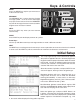
Keys & Controls MENU Press the MENU key anytime you want access to the main test menu. MESSAGE The MESSAGE key is active when the flashing message symbol '* is on the screen. Messages may span several screens. Press the MESSAGE key until all messages have been viewed, and the original screen has been restored. MENU NEXT HELP HELP Press the HELP key when you want context sensitive help. PRINT PRINT Press PRINT to print the display contents to a printer.
Ignition Primary - DIS This test measures the input power and response of the coil. If there are no readings, or they are obviously wrong, check your connections. COMPOSITE SCREEN RPM is read by the black Primary Amps probe from the current pulses drawn by the ignition coils. Battery voltage comes from the red and black Battery Clips. The next display line shows the average ignition primary amps and the average milliSeconds it took for all coils to build up the current during dwell.
Ignition Primary - Distributor IGNITION ENERGY Ignition energy is the quality of the ignition coil inductance. This indicates the coil “kick” in milliVoltSeconds (mVSec). The engine must be cranking or running to produce a readable signal. Typical standard ignition coils produce 25 to 40 mVSec. High energy ignitions have 40 to 60 mVSec. Readings below 20 mVS suggest that inadequate ignition energy is being delivered by the coil. COIL OSCILLATIONS This is an indicator of liveliness in the ignition coil.
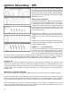
Ignition Secondary - DIS The EngineLink will analyze the ignition and determine the polarity of each of the KV clips. When complete, a screen will advise that the throttle should be opened abruptly. This sets the minimum and maximum readings. The composite screen will appear, showing the average readings for all coils. SPARK BURN DURATION The spark burn duration on a DIS is usually between 0.5 and 1.5 mSec.
Ignition Secondary - Distributor The EngineLink will advise that the throttle should be opened abruptly. This sets the minimum and maximum readings. The composite screen will appear, showing the average readings for all coils. SPARK BURN DURATION The spark burn duration on a DIS is usually between 0.5 and 1.5 mSec. Long burn duration comes from narrow or fouled plug gaps, insulation shorts, low cylinder compression, and rich fuel mixtures.
Hard Start - Distributor Use this test to find the problem area on a no-start engine. If a Distributor ignition was selected during Engine Setup, this screen will appear. The ignition signal for this test comes from the Coil Primary Clip connected to the Coil (-), TACH terminal of the coil. The Amps reading shows starter draw, measured by the Inductive Amp Probe. The probe should be zeroed before testing. To zero, press NEXT and follow the on-screen instructions.
Electronic Compression If a DIS ignition was selected during Engine Setup, the EngineLink will prompt you to disable the fuel supply to prevent the engine from starting during cranking. This is usually done by unplugging the power wire or fuse to the fuel injectors or fuel relay. Many late model vehicles will disable the fuel if wide-open throttle is applied before cranking. The engine may start unexpectedly, so be prepared to release the key and the pedal.
Power Contribution This test measures each cylinder’s contribution to the power output of the engine, without using spark suppression. Power Contribution is not available when Engine Setup "Ignition" is set to Diesel. To run this test on distributor engines, the black Primary Amps probe must be placed around the wire supplying 12 volt power to the ignition coil(s) with the label facing toward the battery feed. There are two screens available. Press SELECT to change between screens.
Power Balance - Automatic/Manual On distributor engines, power balance, or each cylinder’s power contribution relative to the others, can be seen by turning off the spark plugs one at a time and measuring the drop in RPM. In Automatic mode, the Diagnostic Center will suppress ignition to each cylinder in turn, and will display and save the starting and ending RPM for each. The more RPM decrease seen, the more a cylinder must have been contributing.
Starting Charging History An electrical power system test of the engine is the primary feature of this sequenced procedure. Performance of the alternator, battery, and starter are evaluated. This test records battery voltage and amps while the starter cranks the engine for 15 seconds. Then there is a wait to check battery recovery time, followed by a measurement of the charging current when the engine is run at high idle. For accurate results, turn off all lights and accessories.
Volt Amp Meter Amps are measured by the Inductive Amp Probe. Battery voltage is measured at the Battery Power Clips. Auxiliary volts are read with the Auxiliary Meter Lead and referenced to either Battery Power Clip. Press SELECT to change the reference between POS and NEG. Large digits are displayed for enhanced readability. If excessive alternator ripple is detected a message signal will appear on the display. Press the MESSAGE key to display the text.
Auxiliary Meter This general purpose meter is useful for measurement of a variety of voltages and sensor signals. Connect the Auxiliary Meter Lead to a voltage or sensor output. Readings are referenced to the negative vehicle battery terminal through the analyzer’s Battery Clip leads. The DC voltage range is 0 to ±20 volts, with 0.01 volt resolution, and a 10 megohm input impedance. AC signals up to 50 volts peak-to-peak can be measured. Hertz up to 999 and duty cycle % are also displayed.
Fuel Injector Drive Test No readings will be displayed if there are no amps pulses, or if the pickup is reversed, or around both wires of an injector. Peak Amps (PkAmp) shows the peak current driving the injector. It is regulated by the driver. Typical peak readings for one injector are 4 amps for current regulated drivers, and 0.7 amps for resistance limited drivers. Compare one driver bank to another. Build Time, or ramp time in milliSeconds (mS) is affected by the solenoid and the pintle movement.
Run Auto-Test The AutoTest is one of the best and fastest ways to collect comprehensive engine performance data. The analyzer will customize the AutoTest based on the ignition type selected during Engine Setup. The AutoTest sequence steps through the Starting/ Charging History, Ignition Primary, Secondary, and Power Balance tests, and finishes with the Electronic Compression test. Each of the tests is described in detail in the Engine Testing section of this manual, and can be run individually at any time.
Visual Inspection To help inform the car’s owner of additional service items that deserve attention, the condition of many items, from tires and fan belts to wiper blades and lamps, can be indicated on the Visual Inspection Report. This report is also available as part of the AutoTest. Use SELECT to move the cursor between categories. Press NEXT to see list of items in a category. Then use SELECT to choose one of three line endings, OK, LOW or BAD. Press NEXT to accept and move to the next item.
Save Setup This option allows the most frequently used engine setup to be saved in permanent memory. The saved setup will be loaded whenever power is applied to the Diagnostic Center. System Diagnostics Built-in tests allow you to check the operation of various test leads. Select the lead to be tested and follow the screen instructions. Scope Setup The Scope Setup function refers to the two BNC connectors located on the back of the analyzer.
Printing The EngineLink supports printing to a custom thermal printer. Connections for power and data are made through the RJ-45 connector found on the back of the analyzer. Simply plug in the printer and press the PRINT button on the front panel. Individual test results or the autotest results can be printed. Demonstration Mode The EngineLink has a demonstration mode built in.
Typical Readings - Distributor POWER BAL & CONT. STARTING / CHARGING HISTORY IGNITION SECONDARY IGNITION PRIMARY CHARGING HARD START The readings listed here are typical for many common engines, but should be compared to the manufacturer's specifications before extensive repair work is undertaken. 24 Measurement Typical Readings Interpretation Battery Volts (Engine Off) 12.4 to 12.8 Volts Checks battery state of charge. Below 12.3V, charge is low, or load may be on.
Typical Readings The primary readings listed below are for your convenience, and are the result of our own Field Testing. Variations of ±10% should be considered normal. We strongly suggest you test some known good vehicles to get a feel for the readings. Refer to previous page for Starting/Charging and Power test readings, which are the same for DIS and Distributor engines. Company/Engine General Motors 2.0L - I4 2.2L - I4 2.3L - I4 (Quad 4) Other DIS 4 Cylinders 3.0L - V6 3.1L - V6 3.8L - V6 (Type I) 3.
Replacement Parts Power Lead..................................................................................................................................W004-02 Green Amps Probe.......................................................................................................................X000-02 Spark Pickup................................................................................................................................X008-01 Primary Amps Pickup....................................
Technical Support & Service Questions or inquiries about service can be answered by contacting GxT, Inc., at: Toll Free (800) 627-5655. Fax: (231) 627-2727, or repair@gxtauto.com When sending an item to the factory address it to: GxT, Inc., 520 MM Riggs Drive., Cheboygan, MI 49721-1061 Include a note describing the problem. Warranty FERRET BRAND LIMITED PRODUCT WARRANTY GxT, Inc.
SAFETY PRECAUTIONS —Read All Instructions Before Using The Meter— • Always wear eye protection when testing vehicles. Be extra careful near batteries and moving parts. Do not lay tools on a battery. • Battery gas is highly explosive. a. If a battery explodes flush the acid away from persons skin with generous amounts of water. Follow up with a neutralizing solution of baking soda and then more water. Treat clothing, vehicle parts, and equipment similarly.