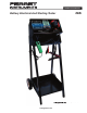
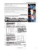
OPERATORʼS MANUAL Battery Electrical And Starting Tester 44 © Copyright 2005, GxT, Inc., All Rights Reserved www.gxtauto.
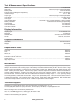
Test & Measurement Specifications RPM.................................................................................................................................................... 0-10,000 RPM RPM Type ......................................................................................................... Inductive, Plug in Field Replaceable Battery Volts ...................................................................................................................................4.0 to 19.
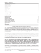
Table of Contents Test & Measurement Specifications .........................................................................................................................2 Display Information ..................................................................................................................................................2 Physical Dimensions ................................................................................................................................................
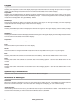
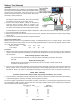
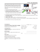
Keypad Amps/Ext V Pressing the Amps/Ext V button will display amperage measurements from the High Amps Probe on the upper display, and the voltage measurements from the external volts leads on the bottom display. Amps/Batt Pressing the Amps/Batt button will display amperage measurements from the High Amps Probe on the upper display, and the voltage as measured from the Battery Clamps. This test configuration is the most widely accepted measurement configuration for typical Battery Testers.
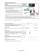
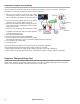
Installing Printer Paper The battery tester has a built in 40 column thermal dot matrix printer that uses paper that is 80mm or 3.18” wide. To Install the paper, remove the printer cover. The easiest pay to load the paper is to cut the paper into an arrowhead. Feel the paper into the printer as shown in the pictures. Once you see the point of the arrowhead appear, grab the tip of the paper and gently pull the paper until the full width of the paper has been fed through the printer. Tear off the paper.
Battery Test (Manual) CAUTION Wear Safety Glasses, Do not break live circuits at the battery terminals, Avoid accidentally shorting the insulated battery terminal to any ground metal. Never put a wrench on a live battery wire terminal. Burns may be the result. Disconnect the battery chassis cable first. 1. Be sure the Load Knob is turned to OFF before connecting the analyzer cables to the battery. Take note of the safety precautions on the back cover of this manual. 2.
Battery Test (Automatic) CAUTION Wear Safety Glasses, Do not break live circuits at the battery terminals, Avoid accidentally shorting the insulated battery terminal to any ground metal. Never put a wrench on a live battery wire terminal. Burns may be the result. Disconnect the battery chassis cable first. 1. Be sure the Load Knob is turned to OFF. 2. Connect the analyzer Battery Clamps to the battery terminals; Red to positive, Black to negative. 3.
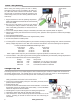
Starter Test (Manual) When testing the starting system, first test for battery performance. With a known good battery, the starter motor, cables and starter solenoid can be checked. Starter amps should not exceed the maximum specified for the vehicle being tested, and the cranking RPM should be satisfactory. 1. Engine should be at normal operating temperature. Make sure all lights and accessories are off and vehicle doors are closed. 2.
Starter Test (Automatic) When testing the starting system, first test for battery performance. With a known good battery, the starter motor, cables and starter solenoid can be checked. Starter amps should not exceed the maximum specified for the vehicle being tested, and the cranking RPM should be satisfactory. 1. Be sure the Load Knob is turned to OFF. 2. Connect the analyzer Battery Clamps to the battery terminals; Red to positive, Black to negative. 3.
Alternator Output Test (Manual) Always compare test results with manufacturerʼs specifications before coming to conclusions regarding the performance or efficiency of charging systems and their components. 1. Be sure the Load Knob is turned to OFF before connecting the analyzer cables to the battery. Take note of the safety precautions on the back cover of this manual. 2. Connect the analyzer Battery Clamps to the battery terminals; Red to positive, Black to negative. 3.
Alternator Output Test (Automatic) Always compare test results with manufacturerʼs specifications before coming to conclusions regarding the performance or efficiency of charging systems and their components. 1. Be sure the Load Knob is turned to OFF. 2. Connect the analyzer Battery Clamps to the battery terminals; Red to positive, Black to negative. 3. With the Amp Probe jaws closed and not around any wires, press the Zero Amps buttons until the Amps Display shows “000” 4.
SAFETY PRECAUTIONS • Always wear eye protection when testing vehicles. Be extra careful near batteries and moving parts. Do not lay tools on a battery. • Battery gas is highly explosive. a. If a battery explodes flush the acid away from persons skin with generous amounts of water. Follow up with a neutralizing solution of baking soda and then more water. Treat clothing, vehicle parts, and equipment similarly. Any acid traces inside equipment must be removed by generous rinsing.