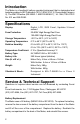
TM Digital Multimeter 94 2000 Count Display Hold Button ON/OFF Button Rotary Switch Common Input Amp Input MilliAmp/ MicroAmp Input Volts/Ohms Diode Input OPERATORʼS MANUAL 1
Introduction The Meter is a handheld, battery operated instrument that is designated and tested according to IEC Publication 1010-1 (EN 61010-1) (Overvoltage Category II), The EMC Directive (EN 50081-1 AND EN 50082-1) , UL 1244, CSA C22.2 No. 231 and ISA-DS82.
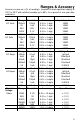
Ranges & Accuracy Accuracy is give as ± ([% of reading] + [number of least significant digits]) at 18°C to 28°C with relative humidity up to 80%, for a period of one year after calibration. Function DC Volts AC Volts Function DC Amps AC Amps Function Voltage Ohms Range Resolution Accuracy 200mV 100µV 0.5% + 1 digit 2V 1mV 0.5% + 1 digit 20V 20V 0.5% + 1 digit 200V 0.1V 0.5% + 1 digit 1000V 1V 0.5% + 1 digit 200mV 100µV 0.8% + 3 digits 2V 1mV 0.8% + 3 digits 20V 10mV 0.8% + 3 digits 200V 0.1V 0.
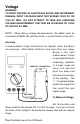
Voltage WARNING! TO AVOID THE RISK OF ELECTRICAL SHOCK AND INSTRUMENT DAMAGE, INPUT VOLTAGES MUST NOT EXCEED 1000V DC OR 750V AC RMS. DO NOT ATTEMPT TO TAKE ANY UNKNOWN VOLTAGE MEASUREMENT THAT MAY BE IN EXCESS OF 1000V DC OR 750V AC RMS. NOTE: When taking voltage measurements, this Meter must be connected in PARALLEL with the circuit, or circuit element under test. Accuracy A measurement range determines the highest value the Meter can measure. Most Meter functions have more than one range.
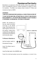
Resistance/Continuity Resistance is measured in Ohms(Ω) and the values can greatly vary from a few Milliohms (mΩ) for contact resistance to millions of ohms for insulators. The Meter can measure down to about 0.1 Ohms and measure as high as 40MΩ. WARNING! TURN OFF POWER AND DISCHARGE ALL CAPACITORS ON CIRCUIT TO BE TESTED BEFORE ATTEMPTING IN CIRCUIT RESISTANCE MEASUREMENTS. ACCURATE MEASUREMENT IS NOT POSSIBLE IF EXTERNAL OR RESIDUAL VOLTAGE IS PRESENT.
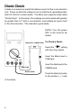
Diode Check A diode is an electronic switch that allows current to flow in one direction only. It turns on when the voltage is over a certain level, generally greater than 0.3 Volts for a silicon diode. The Meter has a special mode called “Diode Check”. In this mode, the readings across the diode will typically be greater than 0.7 Volts in one direction, and indicate an open circuit in the other direction. This indicates a good diode. NOTE: Turn the power OFF to the circuit to be tested.
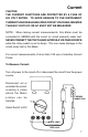
Current CAUTION THE CURRENT FUNCTIONS ARE PROTECTED BY A FUSE OF 600 VOLT RATING. TO AVOID DAMAGE TO THE INSTRUMENT, CURRENT SOURCES HAVING OPEN CIRCUIT VOLTAGES GREATER THAN 600 VOLTS DC OR AC MUST NOT BE MEASURED. NOTE: When taking current measurements, this Meter must be connected In SERIES with the circuit (or circuit element) under test. NEVER CONNECT THE TEST LEADS ACROSS A VOLTAGE SOURCE while the rotary switch is set to Amps. This can cause damage to the circuit under test or this Meter.
SAFETY PRECAUTIONS —Read All Instructions Before Using The Probe— Exceeding the limits of this meter is Dangerous. It will expose you to serious or possible fatal injury. Carefully read and understand the cautions and the specifications limits of this meter. Do not try to measure any voltage that exceeds 1000V DC or 750V AC RMS. Voltages above 60V DC or 25V AC RMS may constitute a serious shock hazard. Circuit tested must be protected by a 15A fuse or circuit breaker.