
User guide

-6-
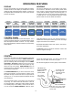
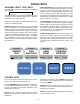
DOING TESTS
1057 RPM msg Bat 13.84
Contrast then START
FUEL INJECTION helps to trouble shoot EFI, PFI, TBI,
and Computer Controlled Carburetor engines. The Duty
Cycle test reads Hertz (Frequency) and Duty Cycle
(Dwell) for use on solenoid equipped carburetors. Also
use for checking pressure, flow, Hall effect, and other
sensors that are specified by these measurements. The
Fuel Injection test measures the milliSeconds of voltage
drive to an injector. See page 11.
Use HARD START to find the problem area on a no start
engine. Ignition Energy indicates the ignition's strength.
Auxiliary Volts is used to confirm that voltage is present
at the ignition. RPM and Battery Voltage are used to
measure the performance of the cranking system. Spe-
cial diagnostics pick out problems with the spark plugs,
wires, cap and rotor. See page 12.
CHARGING STARTING measures cranking speed, volt-
age regulator setting, starter draw, accessory draws, and
alternator output. The Auxiliary Volts is great for voltage
drop tests. Diagnostics monitor the alternator for exces-
sive amps ripple indicating a bad diode or stator. See
page 13.
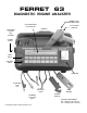
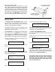
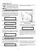
CONTROL KEYS
This lower row of keys select test choices, look up mes-
sages, restart tests, and operate the printer.
Pressing AMP ZERO subtracts whatever the amps read-
ing was so that the reading becomes zero. If amps fails
to work, read the Amp Probe Check procedure in this
manualʼs Service section.
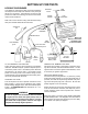
SETUP is used to input information about the engine
being tested, and provides four levels of display contrast
adjustment.
When there are choices in a test, SELECT steps through
the selection. The last displayed choice is made active
by pressing START.
START takes the operation to the next test step. It
continues an operation after some conditions have been
prepared by the operator.
START also clears Min and Max readings on Spark Burn
and Fuel Injection tests.
SENSOR
TEST
02 TPS
SETUP
AMP ZERO
SELECT
MESSAGE
PRINT
DISPLAY
PRINT
AUTOTEST
CHARGING
ST
ARTING
AMPS VOLTS
IGNITION
PRIMARY
COIL MODULE
DWELL VARIATION
AUXILIARYAUXILIARY PER CYLINDER
CRANKING
ANALYSIS
COMPRESSION
BAT. STARTER ALT.
POWER
BALANCE
% RPM DROP
AUTO MANUAL
PER CYLINDER
SP
ARK
BURN
SECONDARY
MSEC SLOPE
PER CYLINDER
HARD
ST
ART
IGNITION VOLTS
AUXILIARY
FUEL
INJECTION
MSEC, % DUTY, HZ
AUXILIARY
START
PAPER
ADVANCE
SENSOR
TEST
02 TPS
SETUP
AMP ZERO
SELECT
MESSAGE
PRINT
DISPLA
Y
PRINT
AUTOTEST
CHARGING
STARTING
AMPS VOLTS
IGNITION
PRIMARY
COIL MODULE
DWELL VARIATION
AUXILIARYAUXILIARY PER CYLINDER
CRANKING
ANALYSIS
COMPRESSION
BAT. STARTER ALT.
POWER
BALANCE
% RPM DROP
AUTO MANUAL
PER CYLINDER
SP
ARK
BURN
SECONDARY
MSEC SLOPE
PER CYLINDER
HARD
START
IGNITION VOLTS
AUXILIARY
FUEL
INJECTION
MSEC, % DUTY, HZ
AUXILIARY
START
PAPER
ADVANCE
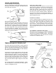
AUXILIARY INPUT TEST KEYS
Typical features of the tests are the RPM and the Battery
Volts readouts.
The RPM reading in the upper left of the display gets the
signal input from the Inductive Spark Pickup. Scaling is
determined by the setup selections.
The Battery Volts reading in the upper right display corner
comes from the Battery Clips.
SENSOR TEST has the following sensor and signal
tests. The Ohmmeter can be used for resistance checks
of spark plug wires or components. The Diode test mea-
sures forward and reverse diode voltage. The Oxygen
Sensor test measures the activity level of the O2 Sensor
voltage. The Throttle Position Sensor test is a computer
aided test to find intermittent TPS sensors. The Wiggle
Test, and GM & Ford Code tests will help you retrieve
trouble codes from some computer controlled engines.
See pages 8-10.