
User guide
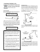

“CHARGING STARTING” KEY
Use this set of tests for general electrical troubleshooting
of starter, alternator and load currents,
along with connection voltage losses.
The special measurements are Inductive
Amps and Auxiliary Volts.
INDUCTIVE AMPS
Before hooking up the Amp Probe see that the reading is
zero. Press AMP ZERO to eliminate zero offsets.
"AMPS" uses the signal from the Inductive Amp Probe.
By placing the pickup around a wire the DC current within
a +/- 600 ampere range can be measured. Resolution
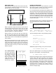
is 1 ampere. An automatic diagnostic check tests for
ripple in the current when it is over 20 amps. If ripple is
high, indicating an alternator with a bad diode or stator,
a message "msg" notifies the user:
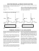
AUXILIARY VOLTS
It receives the signal from the red Auxiliary Clip, and is
referenced to either the positive or negative vehicle bat-
tery terminal through the analyzer Battery Clip leads. The
range is 0 to 20 volts, has 0.01 volt resolution, and has a
10 megohm input impedance to the black Battery Clip.
Press SELECT to change the "Aux>POS" or "Aux>NEG"
reference noted on the display.
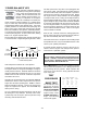
Using the "Aux>GND" reference, it works just as if the
voltmeter had a black clip hooked to the battery negative
terminal.
The "Aux>POS" reference is useful for voltage drop mea-
surements of wiring resistance between battery positive
and connections to accessory loads or from the alterna-
tor output. Readings will be negative to all points on the
vehicle wiring except on the alternator output wire when
it is generating current.
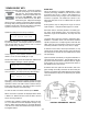
SENSOR
TEST
02 TPS
SETUP
AMP ZERO
SELECT
MESSAGE
PRINT
DISPLA
Y
PRINT
AUTOTEST
CHARGING
ST
ARTING
AMPS VOLTS
IGNITION
PRIMARY
COIL MODULE
DWELL VARIATION
AUXILIARYAUXILIARY PER CYLINDER
CRANKING
ANALYSIS
COMPRESSION
BAT. STARTER ALT.
POWER
BALANCE
% RPM DROP
AUTO MANUAL
PER CYLINDER
SP
ARK
BURN
SECONDARY
MSEC SLOPE
PER CYLINDER
HARD
ST
ART
IGNITION VOLTS
AUXILIARY
FUEL
INJECTION
MSEC, % DUTY, HZ
AUXILIARY
START
PAPER
ADVANCE
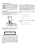
ALTERNATOR OUTPUT VOLTAGE DROP TEST
Charging systems will not keep a battery charged if
the alternator output connections are bad. The fol-
lowing is a basic wiring test for a common defect.
1. Connect the Auxiliary Clip to the alternator output
terminal, and SELECT the "Aux>POS" refer-
ence.
2. Run the engine at about 1500 RPM and switch
the headlights and heater blower on high.
3. If more than 0.5 volt is seen, the voltage drop is
too high and the connection between the alterna-
tor output and battery positive is bad.
4. Then connect the Auxiliary Clip to the alternator
case and SELECT the "Aux>NEG" reference. If
more than 0.2 volt is seen with the engine, lights
and blower still running as before, there is a bad
ground connection to the alternator.
5. Repair any defects found before proceeding.
-13-
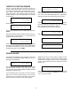
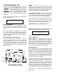
1057 RPM msg Bat 13.84
0 AMPS Aux>NEG 10.34
AMPS RIPPLE ?Alternator?
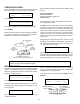
AUX>GND
AUX>POS
POS
12 VOLT
RED
">POS"
AUXILIARY VOLT
REFERENCE
AUX>NEG
AUX>POS
BLACK
GND
12 VOLT
">NEG"
AUXILIARY VOLT
REFERENCE