® TM DIAGNOSTIC ENGINE ANALYZER 63 CONTENTS Charging Starting INTRODUCTION ..................................... 1 Amps, Auxiliary Volts ................... 13 SPECIFICATIONS .................................. 1 Ignition Primary Coil Oscl, Driver, Dwell, .............. 14 OPERATING FEATURES Display ................................................ 2 Spark Burn / Cylinder Control Panel ..................................... 2 Burn MilliSeconds ....................... 16 Printer..............................
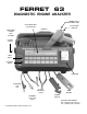
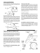
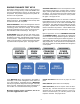
FERRET 63 DIAGNOSTIC ENGINE ANALYZER 48 CHARACTER LCD DISPLAY ANALYZER COVER NOT SHOWN TIMING LIGHT ADVANCE DIAL 2/4 STROKE SWITCH HANDLE COVER LATCH TEST KEYS CONTROL KEYS PRINTER AUXILIARY CLIP red 12 VOLT BATTERY CLIPS PRIMARY COIL CLIP green © Copyright 1994, Ferret Instruments, Inc.
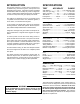
INTRODUCTION SPECIFICATIONS The Engine Analyzer is a time saving instrument for troubleshooting automotive ignition, fuel injection and electrical power systems. It provides computer controlled measurements that are usually only found on diagnostic ʻscopes. Measurement methods have been engineered to reduce hookup effort and give speedy test results. TEST ACCURACY RANGE Volts, Battery ................. 1% ......... 8 to 18 Battery Volts Volts, Aux. [10 meg] ...... 1% .......................
OPERATING FEATURES DISPLAY HOUSING The 2 by 24 character LCD dot matrix display provides a versatile screen for the display of multiple sets of meter outputs as well as data arrayed by cylinder. Contrast can be adjusted with the SETUP key. A cast acrylic window protects the display.
LEADS AND SENSORS 12 VOLT BATTERY CLIP LEAD SET This is a multiconductor cable which draws power from the battery and senses the voltage. It should be the first set of lead clips connected. NO TAG BLACK INDUCTIVE AMPS PROBE The Hall effect Amps Probe senses DC current in wires without having to disturb connections and without introducing any voltage drop. Up to 20 mm (.75”) diameter cables may be read.
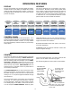
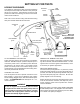
HOOKUP GUIDELINES SETTING UP FOR TESTS BATTERY CLIPS Color labels for matching the cable connections between the analyzer and the clips are marked on the panel just above the connectors. Mismatched connections will prevent the leads from working, but will not cause harm under normal conditions. SPARK PICKUP AMP PROBE COIL / AUXILIARY Take care to find a secure footing and safe lead routing away from exhaust manifolds and fan belts.
NDUCTIVE DC AMP PROBE The reading range is 000 to +/-600 amps DC in 1 amp steps. Starter and alternator output current measurement is the primary application. It also allows the measurement of vehicle accessory currents. Placing the probe on the battery cable, while the engine is off, and then watching the change when operating switches allows checking many loads rapidly. Use AMP ZERO to restore the reading to zero before putting the probe around any wires.
DOING TESTS AUXILIARY INPUT TEST KEYS FUEL INJECTION helps to trouble shoot EFI, PFI, TBI, and Computer Controlled Carburetor engines. The Duty Cycle test reads Hertz (Frequency) and Duty Cycle (Dwell) for use on solenoid equipped carburetors. Also use for checking pressure, flow, Hall effect, and other sensors that are specified by these measurements. The Fuel Injection test measures the milliSeconds of voltage drive to an injector. See page 11.
ENGINE DYNAMICS TEST KEYS CRANKING ANALYSIS has two test sequences to measure Relative Compression, Cranking Volts, Cranking Amps, Cranking RPM, Alternator Amps, and the CCA of the battery. The Compression test finds cylinders with low relative compression, and shows it on the printout bar graph. See pages 20-23. These keys measure engine power cycle functions to find causes of rough running. “PER CYLINDER” tests store the gathered data in memory for after-test review and printout.
“SENSOR TEST” KEY Use SELECT and START to choose tests for measuring ohms or diode volts, measuring oxygen AUXILIARY AUXILIARY AUXILIARY AUXILIARY sensor voltage and crossings, checking FUEL HARD CHARGING SENSOR for irregular throttle position STARTING sensors START INJECTION TEST (TPS), watching for intermittent voltage MSEC, the % DUTY, HZ IGNITION AMPS VOLTS 02 TPS with Wiggle Scope, VOLTS and reading fault OHMS RESISTANCE / SELECT DIODE VOLTS AMP ZERO SETUP START The resistance of a device is measured
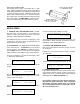
THROTTLE POSITION SENSOR DETECT ON 0.84 v Move SLOWLY to W.O.T This is a computer aided test to check for skips in a position sensor signal sweep. When a position sensor on a throttle or air flow vane is moved from the rest position to the top, the output voltage should move just like the position shaft. The voltmeter reading for this test updates rapidly so that small irregularities are not likely to be missed.
FORD SLOW CODES Ford has different engine test modes for reading codes such as: The Code Reader can be selected to count and display fault code pulse trains from Ford engine computers. KEY-ON ENGINE-OFF ENGINE-RUNNING OUTPUT CYCLING (engine off) WIRE WIGGLE SELECT: FORD SLOW CODES TEST then START Press START. STI and STO are used on other shapes of Ford connectors throughout the world.
“FUEL INJECTION” KEY AUXILIARY AUXILIARY SENSOR TEST FUEL INJECTION 02 TPS AMP ZERO AUXILIARY MSEC, % DUTY, HZ AUXILIARY Injector solenoidCHARGING pulses and sensor sigHARD IGNITION PRIMARY STARTING nal START frequency are read by these tests through the red Auxiliary Clip.
ILIARY UEL CTION % DUTY, HZ TUP “HARD START” KEY If there is a problem with the engine ignition or analyzer hookup, the analyzer will give messages AUXILIARY AUXILIARY PER CYLINDER of the likely causes. Use this testSPARK before HARD CHARGING IGNITION other tests to confirm that the ignition PRIMARY START STARTING BURN hookup is working byMODseeing that the COIL ULE SECONDARY IGNITION VOLTS AMPS VOLTS DWELL VARIATION MSEC SLOPE RPM and Ignition Energy readings are normal.
“CHARGING STARTING” KEY AUXILIARY HARD START NITION VOLTS SELECT Use this set of tests for general electrical troubleshooting AUXILIARY PER CYLINDER PER CYLINDER of starter, alternator and load currents, along with connection losses. CHARGING IGNITION SPARKvoltageCRANKING STARTING PRIMARY ANALYSIS BURN are Inductive The special measurements COIL MODULAuxiliary E COMPRESSION SECONDARY Amps and Volts. DWELL VARIATION AMPS VOLTS BAT. STARTER ALT.
“IGNITION PRIMARY” KEY LIARY RGING RTING VOLTS ART Use to check the input power and response of the ignition coil. SELECT the two screens to PER CYLINDER PER CYLINDER PER CYLINDER see all measurements including Coil IGNITION CRANKING POWER SPARK PRIMARY BURNEnergy ANALYSIS Ignition ("IgEgy"), Coil BALANCE OscillaCOIL MODULE COMPRESSION % RPM DROP tions ("Osc"), Driver Module On Voltage SECONDARY BAT. STARTER ALT.
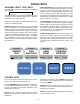
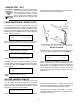
BURN TIME READINGS and PRIMARY PARADE WAVEFORM This figure illustrates the spark plug readings that this engine analyzer extracts from an ignition waveform, and then shows on the display. Tha analyzer would also give two diagnostic messages: GAP Wide, Seq #1 PLUG foul? CAP track? seq #4 The No. 1 cylinder, in the first position of the waveform has a gap in the spark plug wire which causes the short burn time. The next two cylinders are normal.
TION MARY MODULE VARIATION SAGE “SPARK BURN” KEY BURN TIME This is the duration of a spark in milliSeconds. It is affected by the energy available to push the spark current through the plug circuit. If there is little resistance to block the current it will go longer, more resistance and it will burn out quicker. The usual time is about 1.5 milliSeconds (mS) with 0.8 to 2.3 milliSeconds the typical range limits. Measures secondary spark events.
BURN TIME SLOPE Slope tells about the fuel mixture at the end of burn time. Lean makes the voltage rise (plus) and rich makes it fall (minus) during the end of the spark. DIAGNOSTIC MESSAGES Messages are caused by odd combinations of Spark Burn Time and Slope. Follow up on these suggestions with visual inspection and component testing. It is recommended that messages about multiple cylinders be ignored until single cylinder messages have been looked into.
“POWER BALANCE” KEY -----------------------The idle speed motor may have to be unplugged if the ENGINE DATA REPORT test is done at idle. Disconnecting the coolant tempera-----------------------ture sensor will usually cause the computer to operate in ====CRANKING HISTORY==== open-loop fuel control as if the engine were cold. Where SEC RPM BATT AMPS the oxygen sensor is easily reached it can be 1 13.33unplugged 151 to lockup the fuel control. Timing can fixed by 2 326usually 11.
(POWER BALANCE) Press START TEST VARIATIONS The analyzer will check for signals from the ignition. Both a Spark Pickup and Coil Primary TACH signal from an Inductive discharge ignition with a distributor are necessary. If the signals do not match, the analyzer may show: Use SELECT to choose between the automatic sequence test, "Auto-", and the manual cylinder selection "Manual". Then press START.
YLINDER ARK URN ONDARY SLOPE PER ANCE “CRANKING ANALYSIS” KEY CRANKING HISTORY TEST CRANKING HISTORY An power system test of the PER CYLINDER PERelectrical CYLINDER engine is the primary feature of this seCRANKING POWER ANALYSIS BALANCE quenced procedure. Performance meaCOMPRESSION % RPM DROP of the alternator, battery, and surements AUTO MANUAL BAT. STARTER ALT. starter allow comparison to ratings.
STEP TWO BASIC TEST (CRANKING HISTORY) The user should operate the starter by the usual vehicle operator controls. With the automatic suppression, ignition will be held off. Crank ENGINE 15 Seconds The engine may start if ignition compatibility has not been established. Allow it to run for a minute until the situation is resolved. is shown momentarily, then; RPM 8 AMPS Bat 12.
STEP THREE BASIC TEST (CRANKING HISTORY) If the engine was manually disabled, it should be restored during the recovery period. A reminder will be shown after recovery. After the 15 second test the display will show: STOP CRANKING IGNITION OFF Bat 10.14 Sec Restore FUEL or IGNITION When the operator stops cranking, a waiting period begins which checks the voltage recovery time of the battery. Good batteries will spring back in 1 or 2 seconds.
STEP SIX (CRANKING HISTORY) BASIC TEST Display the results and data using START and MESSAGE. The seconds of cranking data have the following display form: 306 RPM 122 AMPS AMPS RIPPLE ?Alternator? Bat 11.57 3 Sec If a battery has a slow recovery or will not accept charging, the CCA performance will not be measured and a message will show: Pressing MESSAGE repeatedly will show the following measurements taken during cranking. Cranking Volts Cranking AMPS 10.
WARNING “CRANKING ANALYSIS” Key THE ENGINE MAY START DURING THE TEST. ELECTRONIC COMPRESSION The cranking-amps-per-cylinder readings of this test give an indication of engine cylinder compression uniformity. This is possible because starter motor amperage is related to the cranking torque, and the cranking torque varies as cylinders go into compression and then spring back . The Cranking Peak-Amps per cylinder test procedure for a standard engine is as follows in the left-hand column.
-----------------------ENGINE DATA REPORT ------------------------ STEP TWO ====CRANKING HISTORY==== (COMPRESSION) SEC RPM BATT AMPS 1 13.33 151 2 326 11.88 129 3 306 11.57 122 With a beep, the display will show: If previous use of the analyzer has verified that the igni4 301 11.35 116 tion can be suppressed and that the Spark Pickup is 5 300 11.17 114 7 292 11.03 113 working, the ignition will be suppressed immediately. 9 291 10.85 112 Otherwise when cranking begins the engine may run 11 289 10.
STEP THREE (CRANKING PEAK-AMPS) BASIC TEST TEST VARIATIONS The saved measurement data is first analyzed for consistency. If it is too irregular the display may show a blank and there will be the following messages: WARNING THE ENGINE MAY START DURING THE TEST Engine Data Unsteady RESULTS UNUSABLE At test completion the ignition will be enabled momentarily to sense the Spark Pickup on cylinder plug #1.
REFERENCE INFORMATION TESTING ENGINES THAT MAKE RADIO INTERFERENCE NOISE: Engines that have metallic (non-resistance) wires going to the ignition distributor usually radiate radio interference. If severe enough it can cause the engine analyzer operation to be disrupted. This usually causes it to return to Setup or to display strange characters. If you have these problems the interference will have to be reduced. Placing resistance in the distributor to coil wire will help.
YLINDER PER CYLINDER NKING LYSIS POWER BALANCE RESSION RTER ALT. % RPM DROP AUTO MANUAL INT PLAY PRINT AUTOTEST PRINTING REPORTS The printed report brings all of the saved data together in a condensed form that is easy to review for signal trends and for comparing cylinder performance tests. -----------------------ENGINE DATA REPORT -----------------------====CRANKING HISTORY==== SEC RPM BATT AMPS 1 13.33 151 2 326 11.88 129 3 306 11.57 122 4 301 11.35 116 5 300 11.17 114 7 292 11.03 113 9 291 10.
VISUAL CHECKLIST At the end of report printing there is the option to add a list of visual inspection items. This is usually done to help inform the car's owner of any defects that should be repaired. Use SELECT to choose one of the three printed line endings. The initial setting for each line is “N/A” which means Not Applicable, and it bypasses printing the item. “OK”, “LOW”, and “BAD” are endings that print along with the list item and indicate what inspection showed it to be.
ANALYZER SERVICE When power is applied to the analyzer it does a selfcheck and will indicate a problem if one is found. Also during operation, checks are done to verify that necessary test signals are working. If a test will not work or the analyzer indicates abnormal operation, the leads associated with the test should be checked as described below before sending it in for service. If the analyzer will not respond to the keys, disconnect power and try again.
SPARK PICKUP CHECK With this test the analyzer is put in a special test mode that produces simulated spark pulses to test the Spark Pickup. At the same time some other internal function self-tests are done. SPARK PICKUP SELF TEST Refer to the connection diagram when doing the following steps. There must not be any connections other than the following: 1638 RPM PULSES GREEN Press START.
Test Key Measurement Typical Readings Interpretation HARD START Battery Volts (Engine Off) 12.4 to 12.8 Volts Checks battery state of charge. Below 12.3V, charge is low, or load may be on. Ignition Energy (Cranking) More than 20 mVSec Shows that there is coil energy available to start the engine. Battery Volts (Engine Running) 13.2 to 15.2 Volts Shows the voltage regulator setting and if the alternator functions.
DIESEL TIMING & RPM The analyzer also provides diesel engine RPM and injection timing tests. The necessary input signals come from the optional Ferret 854 Magnetic TDC Detector, and from a No.1 cylinder Diesel Injection Detector. See instructions provided with the optional detectors. SELECT: Diesel/ 4Stroke Ignition then START The analyzer SETUP has a diesel ignition selection. If selected, analyzer operation is limited to the following tests. Press any test key to find these tests.
SAFETY PRECAUTIONS — Read All Instructions Before Using The Analyzer — • Always wear eye protection when testing vehicles. Be extra careful near batteries and moving parts. Do not lay tools on a battery. • Battery gas is highly explosive. a. If a battery explodes flush the acid away from persons skin with generous amounts of water. Follow up with a neutralizing solution of baking soda and then more water. Treat clothing, vehicle parts, and equipment similarly.