
User manual


9
5-1. Front panel
(1) CV Indicator Lights when the power is on and in constant voltage operation.
(2) CC Indicator Lights when in constant current operation.
(3) Voltage coarse For the coarse adjustment of the output voltage.
(4) Voltage fine For the fine adjustment of the output voltage.
(5) Current coarse For the coarse adjustment of the output current.
(6) Current fine For the fine adjustment of the output current.
(7) “+” output terminal Positive polarity (Red) (MAX. 3A output only).
(8) “GND” terminal Earth and chassis ground (Green).
(9) “–“output terminal Negative polarity (Black) (MAX. 3A output only).
(10) Meter Indicates the output voltage.
(11) Meter Indicates the output current.
(12) Power control On/Off switch.
(13) Current HI/LO control Current indicates HI/LO range selection.
HI range: Output current range is from 0 to rating current.
LO range: Output current range is from 0 to half-rating current.
5-2. Rear panel
(14) Fuse holder
(15) Power socket.
(16) AC selects switch With 115V or 230V voltage and current ranges selection (Refer to the
diagrammatic instruction to prevent mis-operating).
(17) Fan Cooling fan.
(18)
(19)
(20)
(21)
(22)
(23)
(24)
(25)
(26)
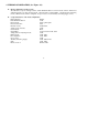
S+ sense terminal
S– sense terminal
+ output terminal
– output terminal
Ground terminal
Remote Control
OVP ADJ
M+ sense terminal
n
M- sense terminal
A positive input voltage remote sense terminal.
A negative input voltage remote sense terminal.
Screw type + output terminal.
Screw type – output terminal.
Screw type ground terminal (connected to case chassis).
Short or open the remote control terminal for output on or off.
Adjust trimmer VR401 to set the OVP value.
A positive output voltage monitor terminal.
A negative output voltage monitor terminal.
Remark: As the front panel has 3A current limit and no remote sense terminal, it is recommended to use rear
output terminal for most of the applications.