
User manual
7
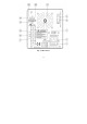
z Description of Circuit Theory
1) +10V Voltage reference circuit:
Start up the circuits of R306 and D302 to ensure the output voltage of OPA U301, PIN 1 is in positive status when power
is on. At this moment, the output voltage of PIN 1 will pass through R307 to maintain the voltage of both ends of
ZENER DIODE ZD301(6.2V) to 6.2V. As OPA has the character of false short circuit, so U301 PIN3=6.2V, refer to the
following formula:
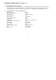
Therefore, the OPA’s output voltage can be changed by adjusting the VR301 as shown in the following formula:
Vref=10V→VR301=1.14kΩ
2) Voltage Adjusting Circuit
The R311, and R313 are voltage feedback attenuating resistors while R312 is to control the output of Reference voltage.
Please refer to the following formula:
If Vref=10V R311=52.3kΩ R313=20kΩ
And the R316, R317, C313, C314, and C315 are compensated circuits for voltage frequency.
3) Current Adjusting Circuit:
The U302 is an Error Amplifier with the gain at:
For example: SPS-1820, Io=20A,R341=10mΩ
Vpin12=Io×R341×A=20×0.01×28.01=5.602V