DC POWER SUPPLY (Switching Mode) SPS-1230/1820/3610/2415/606 USER MANUAL GW INSTEK PART NO.
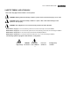
ISO-9001 CERTIFIED MANUFACTURER SAFETY TERMS AND SYMBOLS These terms may appear in this manual or on the product: WARNING. Warning statements identify condition or practices that could result in injury or loss of life. CAUTION. Caution statements identify conditions or practice that could result in damage to this product or other property. WARNING: This equipment is not for measurements performed for CAT II, III and IV.
Terminal iii
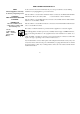
FOR UNITED KINGDOM ONLY As the colours of the wires in main leads may not correspond with the colours marking NOTE This lead/appliance must only identified in your plug/appliance, proceed as follows: be wired by competent persons The wire which is coloured Green & Yellow must be connected to the Earth terminal marke WARNING with the letter E or by the earth symbol or coloured Green or Green & Yellow.
EC Declaration of Conformity We GOOD WILL INSTRUMENT CO.,LTD. No. 7-1, Jhongsing Rd., Tucheng City, Taipei County 236, Taiwan GOOD WILL INSTRUMENT (SUZHOU) CO., LTD. No.69 Lushan Road, Suzhou New District Jiangsu, China.
CONTENTS 1. INTRODUCTION.....................................................................................................................................................................1 2. SPECIFICATION .....................................................................................................................................................................2 2-1. GENERAL ............................................................................................................................
1. INTRODUCTION The series of switching power supplies for measuring instrument have ruled out the inconvenience of big volume and heavyweight of a traditional power supply possess. The output voltage and current is controlled by two variable resistors with coarse and fine regulation for more handy and precise adjustment. Features: z z z z z z With more extensive range of input voltage at 97V~133V (for 115V) and 195V~265V (for 230V).
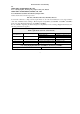
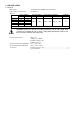
2. SPECIFICATION 2-1. General Main supply Rating, dimension and weight : 115V/230V±15% 50/60Hz (Switch selectable). : See Table 2-1. Table 2-1 MAX. RATING INPUT RATING Voltage Current Watts VA SPS-1230 12V 30A SPS-1820 18V 20A 500 900 SPS-2415 24V 15A SPS-3610 36V 10A SPS-606 60V 6A Dimensions:128(W) × 145(H) × 285(D) mm. Model FUSE STYLE & RATING 115V 230V T 10A 250V T 6.3A 250V WEIGHT kg 3.3 WARNING: Voltage over 60V DC is a lethal shock hazard to the user.
2-2. Constant Voltage Operation (1) Output Voltage ranges from 0 to rating voltage with continuous adjustment. (2) Voltage regulation line regulation≦5mV. load regulation≦5mV. (3) Recovery time≦500μs(50% Load change, minimum load 0.5A). (4) Ripple & Noise≦5mVrms, 100mVp-p (tested by 20MHz oscilloscope.) (5) Temperature coefficient≦100ppm/℃. 2-3. Constant Current Operation (1) Output current ranges from 0 to rating current with continuous adjustment. (2) Current regulation line regulation≦3mA.
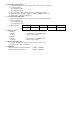
3. PRECAUTIONS BEFORE OPERATION 3.1 Unpacking the Switching Power Supply The instrument has been fully inspected and tested before shipping from the factory. Upon receiving the instrument, please unpack and inspect it to check if there is any damages caused during transportation. If any sign of damage is found, notify the bearer and/or the dealer immediately. 3.2 Checking the Line Voltage The instrument can be used with line voltages shown in the table below.
3.3 Environment The normal ambient temperature range of this instrument is from 0° to 40°C (32° to 104°F). Operation of the instrument above this temperature range may cause damage to the circuits. Do not use the instrument in a place where strong magnetic or electric field exists as it may disturb the measurement. 3.4 Equipment Installation, and Operation Ensure there is proper ventilation for the vents in the SPS power supplies case.
4. THEORY OF OPERATION (See Figure 4-1) z Block Configuration of SPS- System The SPS-Series comprise a Bridge rectifier, a Pulse Width Modulation, a Driver Circuit, a Driver Transformer, a Rectifier Circuit, a Voltage Control Circuit, a Current Shunt, an Output Filter, a Voltage/Current Adjusting Circuit, a Buffer Circuit, an Error Amplifier, an Opto-Isolator, and an Auxiliary Switching Supply and etc. z Component List for each circuit configuration Bridge Rectifier: BD101. Pulse Width Modulation: U102.
z Description of Circuit Theory 1) +10V Voltage reference circuit: Start up the circuits of R306 and D302 to ensure the output voltage of OPA U301, PIN 1 is in positive status when power is on. At this moment, the output voltage of PIN 1 will pass through R307 to maintain the voltage of both ends of ZENER DIODE ZD301(6.2V) to 6.2V. As OPA has the character of false short circuit, so U301 PIN3=6.
z Figure 4-1: Block Diagram 5.
5-1. Front panel (1) CV Indicator (2) CC Indicator (3) Voltage coarse (4) Voltage fine (5) Current coarse (6) Current fine (7) “+” output terminal (8) “GND” terminal (9) “–“output terminal (10) Meter (11) Meter (12) Power control (13) Current HI/LO control Lights when the power is on and in constant voltage operation. Lights when in constant current operation. For the coarse adjustment of the output voltage. For the fine adjustment of the output voltage. For the coarse adjustment of the output current.
Fig.
Fig.
6. OPERATION INSTRUCTIONS 6-1. Precaution (1) AC input AC input should be within the range of line voltage±15% 50/60Hz. WARNING: To avoid electrical shock, the power cord protective grounding conductor must be connected to ground. (2) Installation The machine itself is a heating source , please don't pile up the machine while operation. Keep the machine from other heating source at least for 10cm to assure a sufficient space for radiation in order to extend the life of the machine.
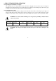
(3) Output Current/Temperature Cure Line Chart: 100% Output Current 50% (%) 20% 10 20 30 40 50 60 0 Environment Temperature (℃) 13
(4) Output Test lead Selection: The Selection of Output Test Lead and Feedback Test Lead: For safety assurance, please select the adequate output test lead according to the following list: UL (CSA) Model 1015 TEW (Twisted Wire) Wire No. AWG Component pc/mm 24 22 20 18 16 14 12 10 11/0.16 17/0.16 21/0.18 34/0.18 26/0.254 41/0.254 65/0.254 65/0.32 Conductor Cross Section Area 2 (mm) 0.22 0.34 0.53 0.87 1.32 2.08 3.29 5.23 Outer Diameter mm 0.64 0.78 0.95 1.21 1.53 2.03 2.35 3.
6-2. Setting Current Limit (1) Determine the maximum safe current for the device to be powered. (2) Temporarily short the (+) and (-) terminals of the power supply together with a test lead. (3) Rotate the COARSE VOLTAGE control away from zero sufficiently to have the CC indicator lightened. (4) Adjust the CURRENT control for the desired current limit. Read the current value on the Ammeter. (5) The current limit (overload protection) has now been preset.
C. D. E. F. Plug power cord into the power outlet. Set Power switch to “ON” position. Adjust “Voltage” and “Current” control to the desired output voltage and current. Connect the external load to the output binding posts. Make sure both “+” and “-” terminals are connected correctly. 6-5. Remote Error Sensing A normal power supply can perform its best load regulation, line regulation, low output impedance, and low output ripple and noise, as well as the rapidly transient recovery response.
The function of the Remote Error Sensing can only be applied to the Constant Voltage mode as shown in Figure 6-3. The feedback point of power supply must start from the load terminal directly. Therefore, the power supply can display its function on the load terminal instead of output terminal. To compensate the voltage drop causing from the test lead, it needs to shift the voltage from the output terminal of power supply, and the voltage on the load terminal remains unchanged.
6-6. Remote Control Short the Remote Control terminal for output ON, and open the Remote Control terminal for output OFF. 6-7. OVP Setting Firstly, adjust the OVP ADJ knob clockwise to the maximum OVP, then adjust output voltage to reach the voltage of OVP. Secondly, adjust the OVP ADJ knob counter-clockwise slowly until the OVP message appears. Then the setting value of OVP is slightly less than the OVP which you intend to set.
7. MAINTENANCE The following instructions are used by qualified personnel only. To avoid electrical shock, do not perform any servicing other than the operating instructions of the manual unless you are qualified to do so. 7-1. Fuse Replacement If the fuse blown, the CV or CC indicators will not light and the power supply will not operate. The fuse should not normally blow unless a problem has developed in the unit.
7-3. Internal adjustments The unit was accurately adjusted at the factory before shipment. So, readjustment is suggested only when the accuracy of circuit is affected by the repair, or when you have the reason to believe that the unit is out of accuracy. The recommended calibration device is a multi-meter with an accuracy of ±0.1% dcv or better. (GOOD WILL model GDM-8145 or equivalent). If readjustment is required, proceed the following procedure. Locations of the adjustments are shown in Fig. 6-1 and Fig.
Fig. 7-1 Adjustment Location Fig. 7-2 Adjustment Location Fig.
7-4 Cleaning To clean the power supply, use a soft cloth dampened in a solution of mild detergent and water. Do not spray cleaner directly onto the instrument, since it may leak into the cabinet and cause damage. Do not use chemicals containing benzene, benzene, toluene, xylem, acetone, or similar solvents. Do not use abrasive cleaners on any portion of the instrument.