
User Manual


LOGIC ANALYZER
209
Using the Logic Analyzer Probes
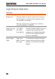
Background
This section will describe how to connect the
digital channels to the device under test.
Connection
1. Turn the DUT off to protect it from being short
circuited when the probes are attached.
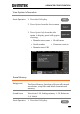
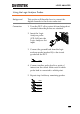
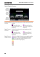
2. Insert the Logic
Analyzer probe
(GTL-16E) into the
Logic Analyzer slot
input.
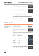
3. Connect the ground lead from the logic
analyzer probe (marked G) to the circuit
ground on the DUT.
GND
G
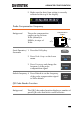
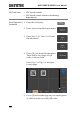
4. Connect another probe lead to a point of
interest on the circuit. Make note of which
probe lead is connected to which point.
5. Repeat step 4 with any remaining probes.
Signal 2
Signal 3
GND
Signal 1
1
2
G
3
….