Multiplex Scanner Box GSB-01/GSB-02 USER MANUAL GW INSTEK PART NO.
This manual contains proprietary information, which is protected by copyright. All rights are reserved. No part of this manual may be photocopied, reproduced or translated to another language without prior written consent of Good Will company. The information in this manual was correct at the time of printing. However, Good Will continues to improve products and reserves the rights to change specification, equipment, and maintenance procedures at any time without notice. Good Will Instrument Co., Ltd. No.
Table of Contents Table of Contents SAFETY INSTRUCTIONS ................................................... 4 GETTING STARTED ........................................................... 9 GSB-01 and GSB-02 Overview .............. 10 Appearance .......................................... 13 Safety Considerations .......................... 18 OPERATION .................................................................... 23 Menu Tree Additions ............................ 24 Test Lead Connection ..............
SAFETY INSTRUCTIONS SAFETY INSTRUCTIONS This chapter contains important safety instructions that you must follow during operation and storage. Read the following before any operation to ensure your safety and to keep the instrument in the best possible condition. Safety Symbols These safety symbols may appear in this manual or on the instrument. WARNING Warning: Identifies conditions or practices that could result in injury or loss of life.
SAFETY INSTRUCTIONS Do not dispose electronic equipment as unsorted municipal waste. Please use a separate collection facility or contact the supplier from which this instrument was purchased. Safety Guidelines General Guideline CAUTION Do not place any heavy object on the instrument. Avoid severe impact or rough handling that leads to damaging the instrument. Do not discharge static electricity to the instrument. Use only mating connectors, not bare wires, for the terminals.
GSB-01/GSB-02 Series User Manual Fuse WARNING Cleaning the GSB-01/GSB-02 Operation Environment Fuse Type: T 2A/250V To ensure fire protection, replace the fuse only with them specified type and rating. Disconnect the power cord before replacing the fuse. Make sure the cause of the fuse blowout is fixed before replacing the fuse. Disconnect the power cord before cleaning. Use a soft cloth dampened in a solution of mild detergent and water. Do not spray any liquid.
SAFETY INSTRUCTIONS Storage environment Disposal Location: Indoor Temperature: -10°C to 70°C Relative Humidity: ≤ 85% (no condensation) Do not dispose this instrument as unsorted municipal waste. Please use a separate collection facility or contact the supplier from which this instrument was purchased. Please make sure discarded electrical waste is properly recycled to reduce environmental impact.
GSB-01/GSB-02 Series User Manual Power cord for the United Kingdom When using the scanner box in the United Kingdom, make sure the power cord meets the following safety instructions.
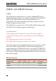
GETTING STARTED GETTING STARTED This chapter describes the scanner box in a nutshell, including its main features and front / rear panel introduction. After going through the overview, please read the safety considerations. CAUTION 5.0 kVAC MAX. 6.0 kVDC MAX. HIGH VOLTAGE GSB-01 CHANNEL POWER Multiplex Scanner Box HI HI HI HI HI HI HI HI LO LO LO LO LO LO LO LO 1 2 3 4 5 6 7 8 PASS FAIL RETURN GSB-01 and GSB-02 Overview .......................................... 10 Lineup ..
GSB-01/GSB-02 Series User Manual GSB-01 and GSB-02 Overview Lineup The aim of these scanner boxes is to allow multiple DUTs to be tested either concurrently or in sequence using the GPT-9800, GPT9900 or GPT-9900A safety testers. The scanner boxes are particularly well suited for multi-point safety testing as well for volume testing on factory floors. The GSB-01 has connections for ACW, DCW and IR testing, while the GSB-02 also includes support for GB testing.
GETTING STARTED Main Features Performance Features Interface 8 HV outputs (6 for GSB-02) 2 GB outputs (GSB-02 only) ACW: 5kV AC DCW: 6kV DC IR: 1kV DC GB: 40A (GSB-02 only) PASS/FAIL LEDs HI LO LEDs Up to 4 scanner boxes can be connected RS-232 interface.
GSB-01/GSB-02 Series User Manual Note 12 GTL-116R x2 GB sense/source H test lead (GSB-02 only) GTL-116B x1 GB sense/source L test lead (GSB-02 only) GTL-235 RS232C Cable Keep the packaging, including the box, polystyrene foam and plastic envelopes should the need arise to return the unit to GW Instek.
GETTING STARTED Appearance GSB-01 Front Panel POWER Button HI / LO Indicators CAUTION 5.0 kVAC MAX. 6.0 kVDC MAX. HIGH VOLTAGE GSB-01 CHANNEL HIGH VOLTAGE Indicator Multiplex Scanner Box HI HI HI HI HI HI HI HI LO LO LO LO LO LO LO LO 1 2 3 4 5 6 7 8 PASS FAIL RETURN POWER Return Terminal Channel Pass/Fail Indicators GSB-02 Front Panel POWER Button HI / LO Indicators CAUTION 5.0 kVAC MAX. 6.0 kVDC MAX.
GSB-01/GSB-02 Series User Manual POWER switch POWER Turns the unit on or off. It is recommended that the unit is powered up before the connected safety tester is turned on. HI LO Indicators The HI/LO Indicators indicate whether a channel is set to the HI or LO output. If neither HI nor LO is lit, it indicates that that channel is disabled. Channel Indicators HIGH VOLTAGE output terminal The Channel Indicators will become lit green on a pass judgment or red on a fail judgment. CAUTION 5.0 kVAC MAX. 6.
GETTING STARTED RETURN, SENSE GSB-02 Only and SOURCE terminals SENSE H RETURN SENSE L GB Rx SOURCE H SOURCE L The RETURN terminal is used for IR, DCW and ACW tests. The SOURCE H, SOURCE L, SENSE H and SENSE L terminals are used for GB tests.
GSB-01/GSB-02 Series User Manual GSB-01 Rear Panel HV1 HV2 INPUT HV1 HV2 HIGH VOLTAGE CH1 CH1 CH3 CH3 OUTPUT HIGH VOLTAGE CH7 CH5 RS232/ RS232/ IN OUT CH7 RS232/IN 5.0 kVAC 6.0 kVDC MAX. SER. NO. LB 5.0 kVAC 6.0 kVDC MAX. CH5 RS232/OUT CH2 CH4 CH6 ENSURE THE POWER IS REMOVED FROM THE INSTRUMENT BEFORE REPLACING THE FUSE CH8 RETURN AC 100 50/60Hz 240V 50VA MAX.
GETTING STARTED HV1, HV2 The HV1 input terminal is used as the primary high voltage input for the scanner box. The HV2 output terminal is used to daisy chain the high voltage output to the next scanner when multiple scanner boxes are used together. CH1 ~ CH8 These channels are connected to the DUTs that are to be tested. The output state is configured from the GPT-9000 safety tester master. Note: For the GSB-02 CH7 and CH8 are used for ground bond testing only.
GSB-01/GSB-02 Series User Manual Safety Considerations Workplace Precautions Background WARNING The GPT-9000 is a high voltage instrument that outputs dangerous voltages. The following section describes precautions and procedures that must be followed to ensure a safe work environment when GSB-01/GSB-02 is connected to the GPT-9000 series safety testers. The GPT-9000 generates voltages in excess of 5kVAC or 6kVDC.
GETTING STARTED 6. Ensure any devices that are adversely affected by magnetic fields are not placed near the tester and scanner box(es).
GSB-01/GSB-02 Series User Manual Operating Precautions Background WARNING The GPT-9000 is a high voltage instrument that outputs dangerous voltages. The following section describes precautions and procedures that must be followed to ensure that the tester along with any conned scanner boxes are operated in a safe manner. The GPT-9000 generates voltages of up to 5kVAC or 6kVDC. Follow all safety precautions, warnings and directions given in the following section when using the instrument. 1.
GETTING STARTED 5. Ensure the earth ground of the line voltage is properly grounded. 6. Only connect the test leads to the HIGH VOLTAGE/SOURCE H/SENSE H terminals before the start of a test. Keep the test leads disconnected at all other times. 7. Always press the STOP button when pausing testing. 8. Do not leave the safety tester unattended. Always turn the power off when leaving the testing area. 9.
GSB-01/GSB-02 Series User Manual Basic Safety Checks Background The GSB-01/GSB-02 are used with high voltage devices and as such, daily safety checks should be made to ensure safe operation. 1. Ensure all test leads are not broken and are free from defects such as cracks or splitting. 2. Ensure the scanner box(es) are always connected to an earth ground. 3.
OPERATION OPERATION Menu Tree Additions ....................................................... 24 Test Lead Connection ...................................................... 25 Connecting GSB-01 Units ....................................................................... 25 Connecting GSB-02 ................................................................................. 29 DUT Connection ...................................................................................... 32 Start Up Procedure ......
GSB-01/GSB-02 Series User Manual Menu Tree Additions When the scanner boxes are added to the GPT-9000 safety tester the scan utility and the scanner configuration menu become available. These additional menu functions are highlighted in the menu tree below. PASS/FAIL result Special manual mode TEST Press S TOP status STOP status Press Press Press STOP2 START STOP READY MANU no.
OPERATION Test Lead Connection This section describes how to connect the GPT-9000 to a number of scanner boxes. It is recommended that only models of the same type are connected together. Connecting GSB-01 Units Background The following will describe how to connect scanner boxes to a GPT-9000 safety tester. Up to 4 scanner boxes can be connected. When wiring the scanner boxes to the safety tester or to each other, only the HV wiring leads (GHT-108) should be used.
GSB-01/GSB-02 Series User Manual AC / DC Withstanding Voltage / Insulation Resistance GPT-9803 Tester PASS FAIL ESC PAGE READY CAUTION HIGH VOLTAGE Safety Tester START TEST 5.0 kVAC MAX. 6.0 kVDC MAX. STOP RETURN HV cable REMOTE POWER MANU/AUTO EDIT/SAVE UTILITY Return cable CAUTION 5.0 kVAC MAX. 6.0 kVDC MAX.
OPERATION Rear Panel 1. Connect the rear panel HV terminals together on the scanners. HV2 (box #1) HV1 (box #2) HV2 (box #2) HV1 (box #3) HV2 (box #3) HV1 (box #4) 2. Connect the Return terminals together on scanners*. Return (box #1) Return (box #2) Return (box #3) Return (box #4) *Box #2 does not need to be connected to box #3 as it was already connected from the front panel. 3. Connect the RS232 ports from the safety tester to each scanner box in a daisy chain using the RS232C cables.
GSB-01/GSB-02 Series User Manual RS232 RS232/IN WARNING SIGNAL I / O RS232 TO AVOID ELECTRIC SHOCK THE POWER CORD PROTECTIVE GROUNDING CONDUCTOR MUST BE CONNECTED TO GROUND. FOR CONTINUED FIRE PROTECTION. REPLACE ONLY WITH SPECIFIED TYPE AND RATED FUSE. NO OPERATOR SERVICEABLE COMPONENTS INSIDE. DO NOT REMOVE COVERS. REFER SERVICING TO QUALIFIED PERSONNEL. Safety Tester GPIB GND ENSURE THE POWER IS REMOVED FROM THE INSTRUMENT BEFORE REPLACING THE FUSE AC POWER MAX.
OPERATION Connecting GSB-02 Background The following will describe how to connect scanner boxes to a GPT-9000 series safety tester with ground bond test support. Up to 4 scanner boxes can be connected. In the examples below only 3 scanner boxes are connected. When wiring the scanner boxes to the safety tester or to each other, only the GB wiring leads (GHT-109) should be used. Front Panel 1. Connect the SOURCE H and SOURCE L terminals on the safety tester to the same terminals on the 1st scanner box. 2.
GSB-01/GSB-02 Series User Manual AC / DC Withstanding Voltage / GPT-9804 Tester Insulation Resistance / Ground Bond PASS FAIL ESC PAGE READY TEST CAUTION 5.0 kVAC MAX. 6.0 kVDC MAX. HIGH VOLTAGE Safety Tester RETURN START STOP REMOTE POWER SENSE H Rx SOURCE H HI HI HI HI HI LO LO LO LO LO 1 2 3 4 5 6 7 HI 5.0 kVAC MAX. 6.0 kVDC MAX. HI-POT IR LO 8 RETURN PASS SENSE H SENSE L FAIL POWER GB Rx SOURCE H SOURCE L CAUTION 5.0 kVAC MAX. 6.0 kVDC MAX.
OPERATION RS232 RS232/IN WARNING SIGNAL I / O RS232 TO AVOID ELECTRIC SHOCK THE POWER CORD PROTECTIVE GROUNDING CONDUCTOR MUST BE CONNECTED TO GROUND. FOR CONTINUED FIRE PROTECTION. REPLACE ONLY WITH SPECIFIED TYPE AND RATED FUSE. NO OPERATOR SERVICEABLE COMPONENTS INSIDE. DO NOT REMOVE COVERS. REFER SERVICING TO QUALIFIED PERSONNEL. Safety Tester GPIB GND ENSURE THE POWER IS REMOVED FROM THE INSTRUMENT BEFORE REPLACING THE FUSE AC POWER MAX.
GSB-01/GSB-02 Series User Manual DUT Connection Background The terminals on the rear panel of the scanner boxes are divided into two sections, input and output. The input section is used (as shown previously) to daisy chain scanner boxes together. The output section is used to connect up to 8 DUTs. The GSB-01 is only used for DCW, ACW and IR testing. The GSB-02 (shown) replaces two high voltage terminals with a pair of SENSE H/SOURCE H terminals for GB testing.
OPERATION Example 1: GB connection with common LO terminals. GTL-116B and GTL-116R test leads are to be used. GB Output connection INPUT HV1 HV2 HIGH VOLTAGE CH1 CH3 OUTPUT HIGH VOLTAGE CH5 RS232/IN 5.0 kVAC 6.0 kVDC MAX. SER. NO. LB 5.0 kVAC 6.0 kVDC MAX. CH7 RS232/OUT HI-POT IR CH2 CH4 ENSURE THE POWER IS REMOVED FROM THE INSTRUMENT BEFORE REPLACING THE FUSE CH6 RETURN GB Rx SENSE H SENSE L SOURCE H SOURCE L AC 100 50/60Hz CH8 240V 50VA MAX.
GSB-01/GSB-02 Series User Manual Example 3: IR, ACW, DCW connections with common return terminal. These tests are best performed sequentially. GHT-116R and GHT-116B test leads are to be used. CH1 to CH8 configured as HI HV1 INPUT HIGH VOLTAGE HV2 CH1 CH3 OUTPUT HIGH VOLTAGE CH5 CH7 RS232/IN 5.0 kVAC 6.0 kVDC MAX. SER. NO. LB 5.0 kVAC 6.0 kVDC MAX. RS232/OUT CH2 CH4 CH6 RETURN CH8 ENSURE THE POWER IS REMOVED FROM THE INSTRUMENT BEFORE REPLACING THE FUSE AC 100 50/60Hz 240V 50VA MAX.
OPERATION Start Up Procedure Startup Background Steps The power up sequence as well as the connections between each scanner box and the safety tester are critical to operate the scanners correctly. 1. Make sure the safety tester and all scanner boxes are turned off. 2. Connect each scanner box to a master safety tester in a daisy chain, as shown on page 25. Make sure the RS232 cables are connected to the correct ports. Make sure the Input and Output cables are connected properly. 3.
GSB-01/GSB-02 Series User Manual Connection Check Background Steps The scanner connection can be checked in the Common Utility menu. 1. Ensure the tester is in VIEW status. MANU = * * * - 0 0 0 MA NU _ N AME FREQ= 6 0 H z H I S E T = 0 1 . 0 0mA 0 100 A CW kV RAMP I R D CW mA =000 . 1S GB RE F # = 0 0 . 0 0mA V I EW T I ME R = 0 0 1 . 0 S 2. Press the UTILITY key. UTILITY 3. Press the SCAN soft-key to view any connected scanner boxes. Any scanner boxes will be displayed in order from 1 to 4.
OPERATION Creating a Test Setup This section describes how to create, edit and run tests using the scanner box interfaces. In principal we will be showing you how to configure the output terminals on the scanner box rear panel. For the GSB-01, each terminal can be configured as either an HV output (hereafter referred to as HI) or as a return terminal (hereafter referred to as LO). For the GSB-02, channels 1 to 6 can be configured to HI or LO terminals as well.
GSB-01/GSB-02 Series User Manual Scanner Box Test Creation Workflow Background The flowchart below shows the basic workflow for creating tests for the scanner boxes.
OPERATION Steps 1. If the tester is in AUTO mode, press and hold the MANU/AUTO key for three seconds to switch to MANU mode. MANU/AUTO The tester can only switch between AUTO and MANU mode when in the VIEW status. 2. Use the scroll wheel to set the MANU number. MANU number MANU = * * * - 0 0 2 MANU _ NAME FREQ= 6 0 H z H I S E T = 0 1 . 0 0mA 0 100 A CW kV RAMP I R D CW mA =000 . 1S GB RE F # = 0 0 . 0 0mA V I EW T I ME R = 0 0 1 . 0 S 3.
GSB-01/GSB-02 Series User Manual Configure the Manual Test Settings Background Steps After a MANU number has been chosen and the tester is in EDIT status, the settings for the current manual test can be configured. 1. To choose the test function, press the ACW, DCW, IR or GB soft-keys. A CW D CW I R GB 2. The test function soft-key is highlighted. 3. Press the UP / DOWN arrow keys to bring the cursor to a function setting. 4. Use the scroll wheel to set the value of the function setting.
OPERATION Configuring the Scanner Box Outputs Background The scanner box output is configured separately for each manual test. This allows you to have one manual test to test multiple DUTs at the same time from a number of scanner boxes. For automatic tests, each manual test can be seen as configuring the output of one step of the automatic test. This section will assume that you are only configuring a single manual test.
GSB-01/GSB-02 Series User Manual 2. Press the PAGE key to bring up the Scanner Configuration Page view for the currently selected manual test. PAGE 3. Press the UP/DOWN and LEFT/RIGHT arrows keys to move the cursor to the desired channel and scanner box. 4. Use the scroll wheel to set the selected channel on the selected scanner box as H or L or X.
OPERATION 6. A test can now be started, see page on 44 to get started. Initialize 7. Pressing the INIT key will initialize all the channels to “X”, disabling all the channels. I N I T Send 8. Pressing SEND will output the channel settings onto the connected scanner boxes. SEND Note If a number of terminals are turned on at the same time, then the voltage/current that is set on the safety tester must be divided by the number of channels that are turned on for the test.
GSB-01/GSB-02 Series User Manual Running a Manual Test Background Note A test can be run when the tester is in READY status. The tester cannot start to run a test under the following conditions: A protection setting has been tripped; when a protection setting has been tripped the corresponding error message is displayed on the screen. The INTERLOCK function is ON and the Interlock key is not inserted in the signal I/O port. The STOP signal has been received remotely.
OPERATION STOP 2. Press the STOP button to put the tester into the READY status. READY status MANU = * * * - 0 0 2 MA NU _ N AME FREQ= 6 0 H z H I S E T = 0 1 . 0 0mA 0 100 A CW kV RAMP I R D CW mA =000 . 1S GB RE F # = 0 0 . 0 0mA READY T I ME R = 0 0 1 . 0 S 3. The READY indicator will be lit blue when in the READY status. READY START 4. Press the START button when the tester is in the READY status. The manual test starts automatically and the tester goes into the TEST status. 5.
GSB-01/GSB-02 Series User Manual 6. The HI or LO indicators of the channels that are turned on for the manual test will be shown on the respective scanner boxes. Ch1 on Ch8 on GSB-01 CHANNEL Multiplex Scanner Box HI HI HI HI HI HI HI HI LO LO LO LO LO LO LO LO 1 2 3 4 5 6 7 8 PASS FAIL 7. The test will start by showing the remaining ramp up time, followed by the remaining test time. The test will continue unit the test is finished or the test is stopped.
OPERATION STOP 9. To put the tester back into READY status, press the STOP button again. Exit TEST Status To exit testing, press the MANU/AUTO key when the tester is in the READY status. The tester will revert to the VIEW status for the current test. MANU = * * * - 0 0 2 MA NU _ N AME FREQ= 6 0 H z H I S E T = 0 1 . 0 0mA 0 100 A CW Note D CW kV RAMP I R mA =000 . 1S GB MANU/AUTO RE F # = 0 0 . 0 0mA V I EW T I ME R = 0 0 1 .
GSB-01/GSB-02 Series User Manual MANU Test Results Background If the test is allowed to run to completion (the test is not stopped or a protection setting is not tripped) then the tester will judge the test(s) as either PASS or FAIL. The pass/fail result of the test(s) is shown on the safety tester display and the scanner box(s). Please note that when multiple DUTs are tested simultaneously and a fail result is produced, it indicates that at least one DUT failed the test.
OPERATION PASS Judgment Safety tester example 1. When the test is judged as PASS, PASS will be displayed, the buzzer will sound, the PASS indicator will be lit green and the channel indicator will be lit green. MANU = * * * - 0 0 2 MA NU _ N AME FREQ= 6 0 H z H I S E T = 0 1 . 0 0mA 0 100 A CW Scanner display example 00 37 kV RAMP I R D CW mA =000 . 1S GB RE F # = 0 0 . 0 0mA PASS T I ME R = 0 0 1 .
GSB-01/GSB-02 Series User Manual FAIL Judgment 3. When the test is judged as FAIL, FAIL will be displayed on the safety tester, the FAIL indicator will be lit red, the channel indicator on the scanner will be lit red and the buzzer will sound. FAIL As soon as a test is judged FAIL, power is cut from the terminals. Safety tester example MANU = * * * - 0 0 2 MANU _ 0 0 2 FREQ= 6 0 H z H I S E T = 0 1 . 0 0mA 0 100 A CW Scanner display example 01 37 kV RAMP I R D CW mA =000 . 1S GB RE F # = 0 0 .
OPERATION Automatic Tests This section describes how to create and run automatic tests for the GSB-01/GSB-02 scanner boxes. An automatic test comprises of up 16 MANU tests that are run sequentially. In order to run an automatic test using the GSB01/GSB-02 scanner boxes, the scanner outputs for each manual test must first be configured, and then each manual test in the automatic test can be stepped through.
GSB-01/GSB-02 Series User Manual MANU = * * * - 0 0 1 MA NU _ N AME AUTO= 0 0 1 - 1 0 0 A U T O _ N AME FREQ= 6 0 H z H I S E T = 0 1 . 0 0mA 0 100 A CW kV RAMP I R D CW mA =000 . 1S GB VIEW status RE F # = 0 0 . 0 0mA V I EW T I ME R = 0 0 1 . 0 S 2. Use the scroll wheel to choose the AUTO number. AUTO # 001~100 AUTO number AUTO= 0 0 1 - 1 0 0 A U T O _ N AME FREQ= 6 0 H z H I S E T = 0 1 . 0 0mA 0 100 A CW kV RAMP I R D CW mA =000 . 1S GB RE F # = 0 0 . 0 0mA V I EW T I ME R = 0 0 1 .
OPERATION 5. Use the scroll wheel to choose a MANU number to add to the automatic test. MANU number 001~100 6. Press the ADD soft-key to add the selected manual test to the automatic test as another step. ADD 7. Repeat steps 5 and 6 for any other tests that you wish to add to the automatic test. 8. A maximum of 16 steps can be added. FULL will be displayed when 16 steps are added. Note The test order can be edited in the Page View menu after the AUTO test is saved. See the user manual for details. 9.
GSB-01/GSB-02 Series User Manual Running an Automatic Test Running an automatic test with the GSB-01/02 scanner boxes is the same as running an automatic test without them. Background The tester cannot start to run an AUTO test under the following conditions: Note Any protection modes have been tripped. The INTERLOCK function is ON and the Interlock key is not inserted in the signal I/O port. The STOP signal has been received remotely.
OPERATION AUTO= 0 0 1 - 1 0 0 A U T O _ N AME FREQ= 6 0 H z H I S E T = 0 1 . 0 0mA 0 100 A CW kV RAMP I R D CW mA =000 . 1S GB RE F # = 0 0 . 0 0mA READY T I ME R = 0 0 1 . 0 S 3. The READY indicator will be lit blue when in the READY status. READY START 4. Press the START button when the tester is in the READY status. The AUTO test starts automatically and the display changes to TEST status. 5. The TEST indicator will be lit orange when in the TEST status. TEST 6.
GSB-01/GSB-02 Series User Manual AUTO= 0 0 1 - 0 0 1 AU TO _ NAME FREQ= 6 0 H z H I S E T = 0 1 . 0 0mA 0 100 A CW RE F # = 0 0 . 0 0mA 00 37 kV RAMP I R D CW mA =000 . 1S GB TEST T I ME R = 0 0 3 . 2 S remaining RAMP time remaining TIMER time PASS/FAIL HOLD 1. If Pass Hold is set to ON or Fail Mode is set to HOLD for a manual test, then the tester will “hold” the testing after a Pass/Fail result for that particular test. HOLD status AUTO= 0 0 1 - 0 0 1 AU TO _ NAME FREQ= 6 0 H z H I S E T = 0 1 .
OPERATION STOP 4. To stop the test when HOLD is displayed on-screen, press the STOP button. Note Stop a Running Test When in HOLD status, only the START and STOP buttons can be pressed, all other keys are disabled. 1. To stop the AUTO test at any time when it is running, press the STOP button. The AUTO test will stop immediately. When the STOP button is pressed, a judgment is not made on the current test and any remaining tests are aborted.
GSB-01/GSB-02 Series User Manual To exit testing, press the MANU/AUTO key when the tester is in the READY status. The tester will revert to the VIEW status for the current automatic test. Exit Testing AUTO= 0 0 1 - 1 0 0 A U T O _ N AME FREQ= 6 0 H z H I S E T = 0 1 . 0 0mA 0 100 A CW D CW kV RAMP I R mA =000 . 1S GB MANU/AUTO RE F # = 0 0 . 0 0mA V I EW T I ME R = 0 0 1 .
OPERATION (excluding skipped tests). A FAIL result for a single step will result in FAIL for the whole automatic test. A STOP. No step can be stopped for a PASS/FAIL judgment to be made. In other words, if a test is stopped, it is judged as neither PASS nor FAIL. No step can contain an ERROR or ILOCK message.
GSB-01/GSB-02 Series User Manual Note FAIL Judgment The Pass Sound setting must to set to ON for the buzzer to sound. When any of the tests have been judged as FAIL, the FAIL indicator will be lit red, the channel indicator for the failed channel(s) will be lit red and the buzzer will sound.
OPERATION View Results 1. When the PASS or FAIL overview table is shown on the screen, turn the scroll wheel right to scroll through each test step. MANU number for current step step number STEP : FREQ= 02 - 00 3 MANU _ NAME 60Hz H I S E T = 0 1 . 0 0mA 0 100 A CW kV 00 37 RAMP I R D CW RE F # = 0 0 . 0 0mA mA =000 . 0S GB PASS T I ME R = 0 0 3 . 2 S PASS/FAIL result 2. Turn the scroll wheel left to return back to the overview table. Return to Ready Status 1.
GSB-01/GSB-02 Series User Manual Exit Testing To exit testing, press the MANU/AUTO key when the tester is in the READY status. The tester will revert to the VIEW status. AUTO= 0 0 1 - 1 0 0 A U T O _ N AME FREQ= 6 0 H z H I S E T = 0 1 . 0 0mA 0 100 A CW 62 D CW kV RAMP I R mA =000 . 1S GB MANU/AUTO RE F # = 0 0 . 0 0mA V I EW T I ME R = 0 0 1 .
OPERATION Common Utility Settings The Common Utility settings are system-wide settings that apply to both MANU tests and AUTO tests. The scanner boxes introduce one new interface setting. Scanner Box Interface Settings Description Steps The interface settings choose the remote interface configuration. USB, RS232 and GPIB (optional) can be selected. With the scanner box(es) installed, remote control is only possible via USB. The RS-232 interfaces are used to link the scanner boxes to the safety tester.
GSB-01/GSB-02 Series User Manual 4. Use the scroll wheel to select SCANNER BOX. 5. Press EDIT/SAVE to save the settings and exit to VIEW status. Note 64 EDIT/SAVE The baud rate setting is fixed to 115200 baud. Note When Interface is set to SCANNER, the remote interface is automatically set to USB. Note The ESC key can be pressed at any time to cancel and exit back to VIEW status.
REMOTE CONTROL REMOTE CONTROL Scanner Commands GSB:CLR ................................................................................................... 65 GSB:SCAN ................................................................................................ 65 GSB:CHANnel .................................................................................. 66 GSB:MEASure .......................................................................................... 67 GSB:HI ...........................
GSB-01/GSB-02 Series User Manual Return parameter Query Example Returns: The connection status and order of each scanner in the following format: <1st>,<2nd>,<3rd>,<4th> Where 01=GSB-01, 02=GSB-02, XX=not connected. GSB:SCAN? >01,02,XX,XX Number #1 scanner box =GSB-01,#2=GSB-02, #3=not connected,#4= not connected. GSB:CHANnel Description Note Query Queries setting state of each scanner box for a specified MANU number. Only applicable in the VIEW or READY status.
REMOTE CONTROL Query Example GSB1:CHAN? > 12345678 >GSB-01:HXXHXXXX >GSB-02:XLXXXLXX >GSB-XX:XXXHXXXX >GSB-XX:XXXHXXXX Indicates that for MANU 001, channel 1 and 4 are set to H for the GSB-01 and that channel 2 and 6 are set to L for the GSB-02. GSB:MEASure Description Note Query Returns the test results for the scanner boxes after the test has completed. Only applicable in the VIEW or READY status.
GSB-01/GSB-02 Series User Manual Query Example GSB1:MEAS? > 12345678 >GSB-01:PXXPXXXX >GSB-02:XFXXXFXX >GSB-XX:XXXXXXXX >GSB-XX:XXXXXXXX Indicates that channel 1 and 4 have passed for the GSB-01 and that channel 2 and 6 have failed for the GSB-02. Set GSB:HI Query Description Sets or queries the HI settings for each scanner box for a selected MANU test number.
REMOTE CONTROL Example2 GSB1: HI SFF000000 Sets Channel 1~8 of scanner 1 to HI. All other channels are off. (FF00000 Hex = 11111111000000000000000000000000 binary) Note Only applicable in the VIEW or READY status. If a channel is set to binary 0, it can still be set to LOW using the GSB:LOW command. Set GSB:LOW Query Description Sets or queries the LOW (return) settings for each scanner box for a selected MANU test number.
GSB-01/GSB-02 Series User Manual Example2 GSB1: LOW SFF000000 Sets Channel 1~8 of scanner 1 to LOW. All other channels are not set. (FF00000 Hex = 11111111000000000000000000000000 binary) Note 70 Only applicable in the VIEW or READY status. If a channel is set to binary 0, it can still be set to HI using the GSB:HI command.
FAQ FAQ • I get a scanner error when I run a test. • The tester will stop testing midway through an automatic test. • When I press the START button the tester will not start testing? I get a scanner error when I run a test. A scanner error indicates that the HV and return terminals haven’t been properly connected between the safety tester and the scanner(s). The tester will stop testing midway through an automatic test. You may have PASS HOLD turned on or FAIL MODE set to HOLD.
GSB-01/GSB-02 Series User Manual If “Interlock” is enabled, the interlock key must be inserted into the signal I/O port on the rear before a test can be started. Lastly, ensure that the Start Ctrl setting is correctly configured in the Common Utility menu. For example, to enable the START button to start a test, ensure that the Start Ctrl setting is set to FRONT PANEL. For more information, contact your local dealer or GWInstek at www.gwinstek.com / marketing@goodwill.com.tw.
APPENDIX APPENDIX Fuse Replacement Steps 1. Turn the instrument off. POWER 2. Take off the power cord and remove the fuse socket using a minus driver. Replace the fuse in the fuse holder.
GSB-01/GSB-02 Series User Manual Error Messages Test Errors The following error messages or messages may appear on the GPT screen when configuring or running tests. Error Messages SCANNER ERR 74 Description Indicates that there is a problem with the scanner connection.
APPENDIX Specifications The specifications apply when the GSB-01/02 is powered on for at least 30 minutes at 15˚C~35˚C.
GSB-01/GSB-02 Series User Manual Dimensions GSB-01 CAUTION 5.0 kVAC MAX. 6.0 kVDC MAX. HIGH VOLTAGE GSB-01 HI HI HI HI HI HI LO LO LO LO LO LO 1 2 3 4 5 6 7 8 POWER 76 PASS FAIL RETURN 100.6 HI LO 88.0 CHANNEL Multiplex Scanner Box HI LO 322.0 349.0 330.0 399.
APPENDIX GSB-02 CAUTION 5.0 kVAC MAX. 6.0 kVDC MAX. HIGH VOLTAGE GSB-02 HI HI HI HI HI HI LO LO LO LO LO LO 2 3 4 5 6 7 8 HI-POT IR PASS SENSE H SENSE L FAIL POWER GB Rx SOURCE H SOURCE L 88.0 HI LO 1 100.6 Multiplex Scanner Box HI LO RETURN CHANNEL 322.0 349.0 330.0 412.
GSB-01/GSB-02 Series User Manual Declaration of Conformity We GOOD WILL INSTRUMENT CO., LTD. No. 7-1, Jhongsing Rd, Tucheng Dist., New Taipei City 236, Taiwan GOOD WILL INSTRUMENT (SUZHOU) CO., LTD. No. 69 Lushan Road, Suzhou New District Jiangsu, China.
INDEX INDEX Accessories ................................. 11 Automatic test create............................................... 51 overview ........................................ 51 results ............................................. 58 running a test ................................ 54 Caution symbol ............................ 4 Cleaning the instrument ............. 6 Declaration of conformity ......... 78 Dimensions ........................... 76, 77 Disposal instructions ...................