
User manual
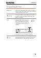
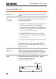

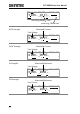

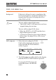

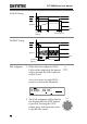

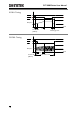
Table Of Contents
- SAFETY INSTRUCTIONS
- GETTING STARTED
- OPERATION
- Menu Tree
- Test Lead Connection
- ACW, DCW and GB Manual Testing
- Choose/Recall a Manual Test Number
- Edit Manual Test Settings
- Setting the Test Function
- Setting the Test Voltage or Test Current
- Setting the Test Frequency
- Setting the Upper and Lower Limits
- Setting a Reference Value
- Setting the Test Time (Timer)
- Setting the Ramp Up Time
- Creating a MANU Test File Name
- Setting the ARC Mode
- Setting PASS HOLD
- Setting FAIL MODE
- Setting MAX HOLD
- Setting the Grounding Mode
- Saving and Exiting EDIT Status
- Running a MANU Test
- PASS / FAIL MANU Test
- Zeroing of the Test Leads (GB only)
- Special MANU Test Mode (000)
- Automatic Tests
- Common Utility Settings
- EXTERNAL CONTROL
- REMOTE CONTROL
- FAQ
- APPENDIX
- INDEX

OPERATION
63
2. Press the STOP button to put the
tester into the READY status.
STOP
I R G B
m A
A CW D CW
E
F R E Q = 0 H z 6
0
100
k V
AER
MT I E = 0 0 1 . 0 SR
0 0 m AER F =# 0 .0
1 . 0 0 m AIH ES = 0T
0 0 . 1 S0A M P =R
D
MM A UN N A_2M A N U = * * * - 0 0
READY status
Y
3. The READY indicator will be lit
blue when in the READY status.
READY
4. Press the START button when the
tester is in the READY status. The
manual test starts automatically
and the tester goes into the TEST
status.
START
5. The TEST indicator will be lit
orange when in the TEST status.
TEST
I R G B A CW D CW
E
F R E Q = 0 H z 6
0
100
k V
SET
MT I E = 0 0 1 . 0 SR
0 0 m AER F =# 0 .0
1 . 0 0 m AIH ES = 0T
0 0 . 1 S0A M P =R
MM A UN N A_2M A N U = * * * - 0 0
TEST status
T
m A
00 00
6. The test will start by showing the remaining
ramp up time, followed by the remaining test
time. The test will continue unit the test is
finished or the test is stopped.