
User manual
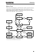
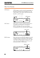

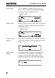

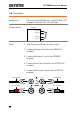
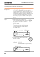
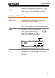
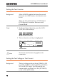
Table Of Contents
- SAFETY INSTRUCTIONS
- GETTING STARTED
- OPERATION
- Menu Tree
- Test Lead Connection
- ACW, DCW and GB Manual Testing
- Choose/Recall a Manual Test Number
- Edit Manual Test Settings
- Setting the Test Function
- Setting the Test Voltage or Test Current
- Setting the Test Frequency
- Setting the Upper and Lower Limits
- Setting a Reference Value
- Setting the Test Time (Timer)
- Setting the Ramp Up Time
- Creating a MANU Test File Name
- Setting the ARC Mode
- Setting PASS HOLD
- Setting FAIL MODE
- Setting MAX HOLD
- Setting the Grounding Mode
- Saving and Exiting EDIT Status
- Running a MANU Test
- PASS / FAIL MANU Test
- Zeroing of the Test Leads (GB only)
- Special MANU Test Mode (000)
- Automatic Tests
- Common Utility Settings
- EXTERNAL CONTROL
- REMOTE CONTROL
- FAQ
- APPENDIX
- INDEX

OPERATION
35
Test Lead Connection
This section describes how to connect the GPT-9000 to a DUT for
withstanding, insulation resistance or ground bond testing.
ACW, DCW, IR Connection
Background
ACW, DCW and IR tests use the HIGH
VOLTAGE terminal and RETURN terminal
with the GHT-114 test leads.
ACW, DCW, IR
Connection
High Voltage terminal
DUT
GPT-9000
Return terminal
Steps
1. Turn the power off on the safety tester.
2. Connect the high voltage test lead(red) to the
HIGH VOLTAGE terminal and screw firmly
into place.
3. Connect the return test lead(white) into the
RETURN terminal and screw the protector bar
into place, as shown below.
HIGH VOLTAGE
Terminal
RETURN
Terminal