
User manual
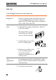
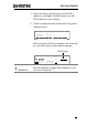
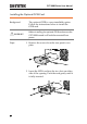
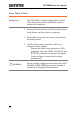
Table Of Contents
- SAFETY INSTRUCTIONS
- GETTING STARTED
- OPERATION
- Menu Tree
- Test Lead Connection
- ACW, DCW and GB Manual Testing
- Choose/Recall a Manual Test Number
- Edit Manual Test Settings
- Setting the Test Function
- Setting the Test Voltage or Test Current
- Setting the Test Frequency
- Setting the Upper and Lower Limits
- Setting a Reference Value
- Setting the Test Time (Timer)
- Setting the Ramp Up Time
- Creating a MANU Test File Name
- Setting the ARC Mode
- Setting PASS HOLD
- Setting FAIL MODE
- Setting MAX HOLD
- Setting the Grounding Mode
- Saving and Exiting EDIT Status
- Running a MANU Test
- PASS / FAIL MANU Test
- Zeroing of the Test Leads (GB only)
- Special MANU Test Mode (000)
- Automatic Tests
- Common Utility Settings
- EXTERNAL CONTROL
- REMOTE CONTROL
- FAQ
- APPENDIX
- INDEX

GPT-9000 Series User Manual
22
Set Up
Line Voltage Connection and Power Up
Background
Before powering up the GPT-9000 ensure the
correct voltage has been selected on the rear
panel. The GPT-9000 supports line voltages of
100V/120V/220V and 230V.
Steps
1. Check the line voltage and the fuse
in the fuse holder.
Page 157
The desired line voltage
should line up with the
arrow on the fuse holder.
2
2
0
1
0
0
120
230
2. Connect the power cord to
the AC voltage input.
2
2
0
1
0
0
120
230
3. If the power cord does not
have an earth ground,
ensure the ground
terminal is connected to an
earth ground.
GND
Warning
Ensure the power cord is connected to an earth
ground. Failure could be harmful to the operator
and instrument.
4. Press the Power button.
POWER