
User manual
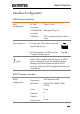
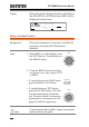
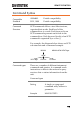
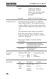

Table Of Contents
- SAFETY INSTRUCTIONS
- GETTING STARTED
- OPERATION
- Menu Tree
- Test Lead Connection
- ACW, DCW and GB Manual Testing
- Choose/Recall a Manual Test Number
- Edit Manual Test Settings
- Setting the Test Function
- Setting the Test Voltage or Test Current
- Setting the Test Frequency
- Setting the Upper and Lower Limits
- Setting a Reference Value
- Setting the Test Time (Timer)
- Setting the Ramp Up Time
- Creating a MANU Test File Name
- Setting the ARC Mode
- Setting PASS HOLD
- Setting FAIL MODE
- Setting MAX HOLD
- Setting the Grounding Mode
- Saving and Exiting EDIT Status
- Running a MANU Test
- PASS / FAIL MANU Test
- Zeroing of the Test Leads (GB only)
- Special MANU Test Mode (000)
- Automatic Tests
- Common Utility Settings
- EXTERNAL CONTROL
- REMOTE CONTROL
- FAQ
- APPENDIX
- INDEX

GPT-9000 Series User Manual
114
Display
When the panel is being remotely controlled via
the USB, RS232 or GPIB interfaces, RMT will be
displayed on the screen.
I R G B A CW D CW
F R E Q = 0 H z 6
0
100
k V
TMR
MT I E = 0 0 3 . 2 SR
0 0 m AER F =# 0 .0
1 . 0 0 m AIH ES = 0T
0 0 . 1 S0A M P =R
2M A UN 0 0_2M A N U = * * * - 0 0
m A
Return to Panel Control
Background
When the instrument is remotely controlled all
panel keys except the STOP button are
disabled.
Steps
1. When RMT is on the display, press
the STOP button. The panel goes to
the READY status.
STOP
2. From the READY status the tester
can go into one of two states: TEST
or VIEW.
To put the tester into VIEW status,
press the MANU/AUTO key.
To put the tester in TEST status,
press the START button. This will
start the manual test/automatic
test. For more details on running a
manual test or automatic test, see
pages 62 and 88, respectively.
MANU/AUTO
START
Note
To put the tester back to RMT, simply issue another
remote control command.