
User manual
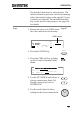
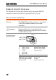
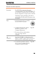
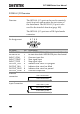
Table Of Contents
- SAFETY INSTRUCTIONS
- GETTING STARTED
- OPERATION
- Menu Tree
- Test Lead Connection
- ACW, DCW and GB Manual Testing
- Choose/Recall a Manual Test Number
- Edit Manual Test Settings
- Setting the Test Function
- Setting the Test Voltage or Test Current
- Setting the Test Frequency
- Setting the Upper and Lower Limits
- Setting a Reference Value
- Setting the Test Time (Timer)
- Setting the Ramp Up Time
- Creating a MANU Test File Name
- Setting the ARC Mode
- Setting PASS HOLD
- Setting FAIL MODE
- Setting MAX HOLD
- Setting the Grounding Mode
- Saving and Exiting EDIT Status
- Running a MANU Test
- PASS / FAIL MANU Test
- Zeroing of the Test Leads (GB only)
- Special MANU Test Mode (000)
- Automatic Tests
- Common Utility Settings
- EXTERNAL CONTROL
- REMOTE CONTROL
- FAQ
- APPENDIX
- INDEX

GPT-9000 Series User Manual
104
External Control Overview
The External Control section describes the front panel REMOTE
terminal connection and the rear panel SIGNAL I/O port.
Remote Terminal Overview
Overview
The REMOTE terminal connector is a standard
5-pin DIN terminal suitable for a remote
controller.
WARNING
Keep any cables that are connected to the
REMOTE terminal away from the HIGH VOLTAGE
and RETURN terminals.
Pin Assignment
and Connection
REMOTE
1
2
3
4
5
RMT_START
RMT_STOP
Pin
Pin name
Description
1
RMT_STOP
Remote Stop signal
2
RMT_START
Remote Start signal
3
COM
Common line
4
Not used
5
Not used
Signal Properties
High level input voltage
2.4V~3.3V
Low level input voltage
0~0.8V
Input period
minimum of 1ms