
User manual
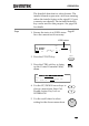


Table Of Contents
- SAFETY INSTRUCTIONS
- GETTING STARTED
- OPERATION
- Menu Tree
- Test Lead Connection
- ACW, DCW and GB Manual Testing
- Choose/Recall a Manual Test Number
- Edit Manual Test Settings
- Setting the Test Function
- Setting the Test Voltage or Test Current
- Setting the Test Frequency
- Setting the Upper and Lower Limits
- Setting a Reference Value
- Setting the Test Time (Timer)
- Setting the Ramp Up Time
- Creating a MANU Test File Name
- Setting the ARC Mode
- Setting PASS HOLD
- Setting FAIL MODE
- Setting MAX HOLD
- Setting the Grounding Mode
- Saving and Exiting EDIT Status
- Running a MANU Test
- PASS / FAIL MANU Test
- Zeroing of the Test Leads (GB only)
- Special MANU Test Mode (000)
- Automatic Tests
- Common Utility Settings
- EXTERNAL CONTROL
- REMOTE CONTROL
- FAQ
- APPENDIX
- INDEX

EXTERNAL CONTROL
109
Using the Interlock Key
Background
When the INTERLOCK function is set to ON,
tests are only allowed to start when both
Interlock pins on the signal I/O port are
shorted. Using the Interlock key will short the
INTERLOCK1 and INTERLOCK2 pins on the
signal I/O port.
See page 106 for the Signal I/O pin assignment.
Panel operation
1. Insert the Interlock
key into the SIGNAL
I/O port on the rear
panel.
2. Set the INTERLOCK option to ON
in the Common Utility.
Page 100
Note
With INTERLOCK set to ON, the tester can now
only start a test when the Interlock key is
connected. Do not remove the interlock after
starting a test. It must be connected after a test
has started or is running.
Set INTERLOCK to OFF to disable this feature.