
User manual
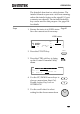


Table Of Contents
- SAFETY INSTRUCTIONS
- GETTING STARTED
- OPERATION
- Menu Tree
- Test Lead Connection
- ACW, DCW and GB Manual Testing
- Choose/Recall a Manual Test Number
- Edit Manual Test Settings
- Setting the Test Function
- Setting the Test Voltage or Test Current
- Setting the Test Frequency
- Setting the Upper and Lower Limits
- Setting a Reference Value
- Setting the Test Time (Timer)
- Setting the Ramp Up Time
- Creating a MANU Test File Name
- Setting the ARC Mode
- Setting PASS HOLD
- Setting FAIL MODE
- Setting MAX HOLD
- Setting the Grounding Mode
- Saving and Exiting EDIT Status
- Running a MANU Test
- PASS / FAIL MANU Test
- Zeroing of the Test Leads (GB only)
- Special MANU Test Mode (000)
- Automatic Tests
- Common Utility Settings
- EXTERNAL CONTROL
- REMOTE CONTROL
- FAQ
- APPENDIX
- INDEX

EXTERNAL CONTROL
107
Output
Connection
PIN 6 OUTPUT_TEST
PIN 9 OUTPUT_COM
PIN 8 OUTPUT_PASS
PIN 7 OUTPUT_FAIL
Signal Properties
Input Signals
High level input voltage
5V ~ 32V
Low level input voltage
0V ~ 1V
Low level input current
Maximum of -5mA
Input period
Minimum of 1ms
Output Signals
Output Type
Relay form A
Output Rated Voltage
30VDC
Maximum output current
0.5A