
User manual
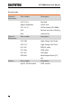
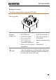
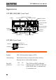
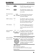
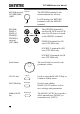
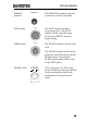
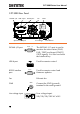
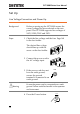
Table Of Contents
- SAFETY INSTRUCTIONS
- GETTING STARTED
- OPERATION
- Menu Tree
- Test Lead Connection
- Manual Testing
- Choose/Recall a Manual Test Number
- Edit Manual Test Settings
- Setting the Test Function
- Setting the Test Voltage or Test Current
- Setting the Test Frequency
- Setting the Upper and Lower Limits
- Setting a Reference Value
- Setting the Test Time (Timer)
- Setting the Ramp Up Time
- Creating a MANU Test File Name
- Setting the ARC Mode
- Setting PASS HOLD
- Setting FAIL HOLD
- Setting MAX HOLD
- Setting the Grounding Mode
- Saving and Exiting EDIT Status
- Running a MANU Test
- PASS / FAIL MANU Test
- Zeroing of the Test Leads (GB only)
- Special MANU Test Mode (000)
- Common Utility Settings
- Automatic Tests
- EXTERNAL CONTROL
- REMOTE CONTROL
- FAQ
- APPENDIX
- INDEX

GPT-9000 Series User Manual
18
GPT-9000 Rear Panel
SIGNAL I/O USB A port RS232 port Fan
Fuse selectorLine voltage
Optional GPIB port
GND
TO AVOID ELECTRIC SHOCK THE POWER CORD
PROTECTIVE GROUNDING CONDUCTOR MUST BE
ONLY WITH SPECIFIED TYPE AND RATED FUSE
.
NO OPERATOR SERVICEABLE COMPONENTS INSIDE
.
DO NOT REMOVE COVERS REFER SERVICING TO
FOR CONTINUED FIRE PROTECTION
.
REPLACE
CONNECTED TO GROUND
.
QUALIFIED PERSONNEL.
WARNING
AC
LINE VOLTAGE
100V
230V
220V
120V
SELECTION
207~250V
RANGE
90~110V
198~242V
108~132V
(50/60 Hz)
T 5A
250V
FUSE
POWER MAX.
500VA
GND
SIGNAL I / O RS232
SER. NO . LB
ENSURE THE POWER IS REMOVED FROM
THE INSTRUMENT BEFORE REPLACING THE FUSE
GPIB
T 2.5A
250V
SIGNAL I/O port
SIGNAL I / O
The SIGNAL I/O port is used to
monitor the tester status (PASS,
FAIL, TEST) and input (START/
STOP signals). It is also used with
the Interlock key.
USB A port
Used for remote control.
RS232 interface
port
RS232
Used for remote control and
firmware updates.
Fan
Exhaust fan.
GND
GND
Connect the GND (ground)
terminal to the earth ground.
Line voltage input
220
230
100
120
Line voltage input:
100/120/220/230VAC ±10%