
User manual
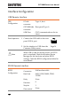
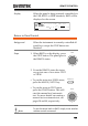
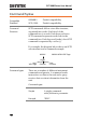
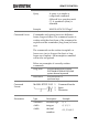
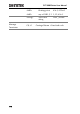
Table Of Contents
- SAFETY INSTRUCTIONS
- GETTING STARTED
- OPERATION
- Menu Tree
- Test Lead Connection
- Manual Testing
- Choose/Recall a Manual Test Number
- Edit Manual Test Settings
- Setting the Test Function
- Setting the Test Voltage or Test Current
- Setting the Test Frequency
- Setting the Upper and Lower Limits
- Setting a Reference Value
- Setting the Test Time (Timer)
- Setting the Ramp Up Time
- Creating a MANU Test File Name
- Setting the ARC Mode
- Setting PASS HOLD
- Setting FAIL HOLD
- Setting MAX HOLD
- Setting the Grounding Mode
- Saving and Exiting EDIT Status
- Running a MANU Test
- PASS / FAIL MANU Test
- Zeroing of the Test Leads (GB only)
- Special MANU Test Mode (000)
- Common Utility Settings
- Automatic Tests
- EXTERNAL CONTROL
- REMOTE CONTROL
- FAQ
- APPENDIX
- INDEX

REMOTE CONTROL
105
Pin Assignment
1 2 3 4 5
6 7 8 9
1: No connection
2: RxD (Receive Data)
3: TxD (Transmit Data)
4: No connection
5: GND
6-9: No connection
Connection
PC
GPT-9000
DB9 Pin
Signal
Signal
DB9Pin
2
RxD
TxD
3
3
TxD
RxD
2
5
GND
GND
5
Panel operation
1. Connect the Null modem cable to
the rear panel RS232 port.
RS232
2. Set the interface to RS232 from the
Common Utility menu.
Page 74
GPIB Remote Interface
GPIB
Configuration
Address
0-30
Panel operation
1. Connect the GPIB cable to the
rear panel GPIB port.
GPIB
2. Set the interface to GPIB and set
the GPIB address from the
Common Utility menu.
Page 74