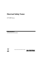
Electrical Safety Tester GPT-9000 Series USER MANUAL GW INSTEK PART NO.
This manual contains proprietary information, which is protected by copyright. All rights are reserved. No part of this manual may be photocopied, reproduced or translated to another language without prior written consent of Good Will company. The information in this manual was correct at the time of printing. However, Good Will continues to improve products and reserves the rights to change specification, equipment, and maintenance procedures at any time without notice. Good Will Instrument Co., Ltd. No.
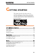
SAFETY INSTRUCTIONS Table of Contents SAFETY INSTRUCTIONS .................................................. 5 GETTING STARTED .......................................................... 9 GPT-9000 Series Overview ................... 10 Appearance .......................................... 14 Set Up .................................................. 20 OPERATION .................................................................. 27 Menu Tree ............................................
GPT-9000 Series User Manual INDEX ..........................................................................
SAFETY INSTRUCTIONS SAFETY INSTRUCTIONS This chapter contains important safety instructions that you must follow during operation and storage. Read the following before any operation to ensure your safety and to keep the instrument in the best possible condition. Safety Symbols These safety symbols may appear in this manual or on the instrument. WARNING Warning: Identifies conditions or practices that could result in injury or loss of life.
GPT-9000 Series User Manual Do not dispose electronic equipment as unsorted municipal waste. Please use a separate collection facility or contact the supplier from which this instrument was purchased. Safety Guidelines General Guideline CAUTION Do not place any heavy object on the GPT-9000. Avoid severe impact or rough handling that leads to damaging the GPT-9000. Do not discharge static electricity to the GPT9000. Use only mating connectors, not bare wires, for the terminals.
SAFETY INSTRUCTIONS Cleaning the GPT-9000 Operation Environment Disconnect the power cord before cleaning. Use a soft cloth dampened in a solution of mild detergent and water. Do not spray any liquid. Do not use chemicals containing harsh material such as benzene, toluene, xylene, and acetone.
GPT-9000 Series User Manual Power cord for the United Kingdom When using the safety tester in the United Kingdom, make sure the power cord meets the following safety instructions.
GETTING STARTED GETTING STARTED This chapter describes the safety tester in a nutshell, including its main features and front / rear panel introduction. After going through the overview, please read the safety considerations in the Set Up chapter. AC / DC Withstanding Voltage / Insulation Resistance GPT-9803 Tester PASS FAIL ESC PAGE READY TEST CAUTION 5.0 kVAC MAX. HIGH VOLTAGE 6.0 kVDC MAX. START STOP RETURN REMOTE POWER MANU/AUTO EDIT/SAVE UTILITY GPT-9000 Series Overview ...............
GPT-9000 Series User Manual GPT-9000 Series Overview Series lineup The GPT-9000 Series Safety Testers are AC/DC withstanding voltage, insulation resistance and ground bond safety testers. The GPT-9801 is an AC withstanding voltage tester, the GPT-9802 is an AC/DC withstanding voltage tester and the GPT-9803 is an AC/DC withstanding voltage and insulation resistance tester. The GPT-9804 includes all the functions of the other models as well as ground bond testing.
GETTING STARTED Main Features Performance ACW: 5kVAC DCW: 6kVDC Features Interface IR: 50V~1000V (50V steps) GB: 3A~30A Ramp up time control Safety discharge 100 test conditions (MANU mode) 100 automatic tests (AUTO mode) Over temperature, voltage and current protection Pass, Fail, Test, High Voltage and Ready indicators PWM output (90% efficiency, increased reliability) Interlock (configurable).
GPT-9000 Series User Manual Accessories Standard Accessories Optional Accessories Options 12 Part number Description GHT-114 x1 Test lead Region dependent Power cord GTL-115 x1 GB Test leads (GPT-9804) N/A Remote terminal male plug N/A Interlock key Part number Description GHT-205 High Voltage Test Probe GHT-113 High Voltage Test Pistol GTL-232 RS232C cable GTL-248 GPIB cable GTL-247 USB cable GRA-402 Rack Adapter Panel (19”, 4U) Part number Description Opt.
GETTING STARTED Package Contents Check the contents before using the GPT-9000. Opening the box Contents (single unit) GPT-9000 unit GHT-114 test leads x1 Quick Start guide User manual CD GTL-115 test leads x1 (GPT-9804) Remote terminal male CTC (Calibration plug Traceable Certificate) Interlock key Power cord x1 (region dependent) Note Keep the packaging, including the box, polystyrene foam and plastic envelopes should the need arise to return the unit to GW Instek.
GPT-9000 Series User Manual Appearance GPT-9801/9802/9803 Front Panel PASS/FAIL indicators Function keys Directional keys Display AC / DC Withstanding Voltage / Insulation Resistance GPT-9803 Tester PASS FAIL ESC PAGE READY READY indicator TEST CAUTION 5.0 kVAC MAX. HIGH VOLTAGE 6.0 kVDC MAX.
GETTING STARTED ESC key PAGE key The ESC key is used to exit out of a menu or cancel a setting. ESC The PAGE key is used to view automatic test information and test results. PAGE The directional arrow keys are used to navigate menus and parameter settings. Directional arrow keys READY indicator READY The READY indicator is lit when the tester is ready to begin testing. The STOP button is used to put the tester into READY status. TEST indicator TEST The TEST indicator is lit when a test is on.
GPT-9000 Series User Manual RETURN terminal GPT-9801/9802 /9803 RETURN The RETURN terminal is the return terminal for all tests. For GB testing, the RETURN terminal is also the SENSE L terminal. RETURN/ SENSE L, SENSE H, SOURCE L, SOURCE H terminal (GPT-9804) RETURN SENSE H Rx SOURCE H SENSE L SOURCE L The RETURN terminal is used for IR, DCW and ACW tests. For GB tests, it is used as the SENSE L terminal. SENSE H terminal for GB tests. GPT-9804 only. SOURCE L terminal for GB tests. GPT-9804 only.
GETTING STARTED REMOTE terminal STOP button START button REMOTE STOP START The REMOTE terminal is used to connect to a remote controller. The STOP button is used to stop/cancel tests. The STOP button will also put the safety tester in the READY status to begin testing. The START button is used to start tests. The START button can be used to start tests when the tester is in the READY status. Pressing the START button will put the tester in the TEST status. POWER switch POWER Turns the power on.
GPT-9000 Series User Manual GPT-9000 Rear Panel SIGNAL I/O USB A port RS232 port Fan GND WARNING SIGNAL I / O TO AVOID ELECTRIC SHOCK THE POWER CORD PROTECTIVE GROUNDING CONDUCTOR MUST BE CONNECTED TO GROUND . FOR CONTINUED FIRE PROTECTION REPLACE ONLY WITH SPECIFIED TYPE AND RATED FUSE . NO OPERATOR SERVICEABLE COMPONENTS INSIDE . DO NOT REMOVE COVERS . REFER SERVICING TO QUALIFIED PERSONNEL . RS 232 GND GPIB ENSURE THE POWER IS REMOVED FROM THE INSTRUMENT BEFORE REPLACING THE FUSE AC POWER MAX.
GETTING STARTED Line voltage fuse 230 120 220 100 Optional GPIB port GPIB Line voltage selector and fuse: 100V/120V T5A 250V 220V/230V T2.5A 250V Optional GPIB interface for remote control.
GPT-9000 Series User Manual Set Up Line Voltage Connection and Power Up Background Steps Before powering up the GPT-9000 ensure the correct voltage has been selected on the rear panel. The GPT-9000 supports line voltages of 100V/120V/220V and 230V. 1. Check the line voltage and the fuse Page 146 in the fuse holder. The desired line voltage should line up with the arrow on the fuse holder. 120 120 100 GND Ensure the power cord is connected to an earth ground.
GETTING STARTED 5. When the unit is powering up, all the LED indicators will light. Check to make sure all 5 LED indicators are working. 6. Check to make sure the System Self Test passes without errors. S Y S T EM S E L F TEST S y s t em Ch e c k i n g . . . Ha r dwa r e Che c k i ng . . . F i r mw a r e C h e c k i n g . . . After the System Self Test completes, the tester will go into VIEW status and be ready to operate. VIEW status MANU = * * * - 0 0 2 MA NU _ N AME FREQ= 6 0 H z H I S E T = 0 1 .
GPT-9000 Series User Manual Installing the Optional GPIB Card Background WARNING Steps The optional GPIB is a user-installable option. Follow the instructions below to install the GPIB card. Before installing the optional GPIB card ensure the GPT-9000 turned is off and disconnected from power. 1. Remove the screws from the rear panel cover plate. 2. Insert the GPIB card into the two slots on either side of the opening. Push the card gently until it is fully inserted.
GETTING STARTED Workplace Precautions Background WARNING The GPT-9000 is a high voltage instrument that outputs dangerous voltages. The following section describes precautions and procedures that must be followed to ensure a safe work environment. The GPT-9000 generates voltages in excess of 5kVAC or 6kVDC. Follow all safety precautions, warnings and directions given in the following section when using the GPT-9000. 1. Only technically qualified personnel should be allowed to operate the safety tester.
GPT-9000 Series User Manual Operating Precautions Background WARNING The GPT-9000 is a high voltage instrument that outputs dangerous voltages. The following section describes precautions and procedures that must be followed to ensure that the tester is operated in a safe manner. The GPT-9000 generates voltages of up to 5kVAC or 6kVDC. Follow all safety precautions, warnings and directions given in the following section when using the GPT-9000. 1.
GETTING STARTED 5. Ensure the earth ground of the line voltage is properly grounded. 6. Only connect the test leads to the HIGH VOLTAGE/SOURCE H/SENSE H terminals before the start of a test. Keep the test leads disconnected at all other times. 7. Always press the STOP button when pausing testing. 8. Do not leave the safety tester unattended. Always turn the power off when leaving the testing area. 9.
GPT-9000 Series User Manual Basic Safety Checks Background The GPT-9000 is a high voltage device and as such, daily safety checks should be made to ensure safe operation. 1. Ensure all test leads are not broken and are free from defects such as cracks or splitting. 2. Ensure the safety tester is always connected to an earth ground. 3.
OPERATION OPERATION Menu Tree...................................................................... 29 Menu Tree Overview ...............................................................................30 Test Lead Connection ..................................................... 33 ACW, DCW, IR Connection ....................................................................33 GB Connection ..........................................................................................34 Manual Testing ..........
GPT-9000 Series User Manual Buzzer Settings ......................................................................................... 73 Interface Settings ...................................................................................... 74 Control Settings ........................................................................................ 76 Automatic Tests .............................................................. 79 Choose/Recall an Automatic Test ..........................................
OPERATION Menu Tree This section describes the overall structure of the operation statuses and modes for the GPT-9000 safety testers. The testers have two main testing modes (MANU, AUTO) and 5 main operation statuses (VIEW, EDIT, READY, TEST and STOP).
GPT-9000 Series User Manual Menu Tree Overview VIEW status VIEW status is used to view the parameters of the selected manual test/automatic test. The VIEW status is also used to put the tester into MANU or AUTO mode. AUTO= 0 0 1 - 0 0 2 A U T O _ N AME MANU = * * * - 0 0 2 MA NU _ N AME FREQ= 6 0 H z H I S E T = 0 1 . 0 0mA 0 100 A CW EDIT status kV RAMP I R D CW mA =000 . 1S GB VIEW status RE F # = 0 0 . 0 0mA ARC = OF F V I EW T I ME R = 0 0 1 .
OPERATION TEST status TEST status is active when a MANU test or AUTO test is running. Pressing STOP will cancel the MANU test or the remaining steps in an AUTO test. TEST status MANU = * * * - 0 0 2 MA NU _ N AME FREQ= 6 0 H z H I S E T = 0 1 . 0 0mA 0 100 A CW STOP status kV 00 33 RAMP I R D CW mA =000 . 1S GB RE F # = 0 0 . 0 0mA ARC= OF F TEST T I ME R = 0 0 1 . 0 S STOP status is shown when a manual test or automatic test did not finish running and has been stopped by the operator.
GPT-9000 Series User Manual AUTO mode AUTO indicates that the tester is in AUTO mode. AUTO mode is for creating/running a sequence of up to 16 MANU tests. AUTO mode AUTO= 0 0 3 - 0 0 2 AU TO _ NAME FREQ= 6 0 H z H I S E T = 0 1 . 0 0mA 0 100 A CW MANU mode kV RAMP I R D CW mA =000 . 1S GB RE F # = 0 0 . 0 0mA ARC = OF F ED I T T I ME R = 0 0 1 . 0 S ADD MANU mode is used to create and/or execute a single test. MANU indicates that the manual test mode is active.
OPERATION Test Lead Connection This section describes how to connect the GPT-9000 to a DUT for withstanding, insulation resistance or ground bond testing. ACW, DCW, IR Connection Background ACW, DCW, IR Connection ACW, DCW and IR tests use the HIGH VOLTAGE terminal and RETURN terminal with the GHT-114 test leads. GPT-9000 High Voltage terminal DUT Return terminal Steps 1. Turn the power off on the safety tester. 2.
GPT-9000 Series User Manual GB Connection Background GB Connection GB tests use the SENSE H/L and SOURCE H/L terminals with the GTL-115 test leads. GPT-9000 Source H Sense H DUT Source L Sense L Steps 1. Turn the power off on the safety tester. 2. Connect the Sense H lead to the SENSE H terminal. 3. Connect the Sense L lead to the SENSE L terminal. 4. Connect the Source H lead to the SOURCE H terminal. 5. Connect the Source L lead to the SOURCE L terminal.
OPERATION Manual Testing This section describes how to create, edit and run a single ACW, DCW, IR or GB safety test. Each Manual setting described in this chapter only applies to the selected manual test – no other manual tests are affected. Each manual test can be stored/recalled to/from one of 100 memory locations. Each stored manual test can be used as a test step when creating an AUTO test (page 79). Choose/Recall a Manual Test number → from page 36. Edit Manual Test Settings → from page 37.
GPT-9000 Series User Manual Choose/Recall a Manual Test Number Background Steps ACW, DCW, IR and GB tests can only be created in the MANU (manual) mode. MANU number 001 to 100 can be saved and thus be loaded when editing/creating a MANU test or AUTO test. MANU number 000 is a special mode. See page 67 for details on the special mode. 1. If the tester is in AUTO mode, press and hold the MANU/AUTO key for three seconds to switch to MANU mode.
OPERATION Note The MANU number can only be chosen in VIEW status. If in the EDIT status, switch to the VIEW status by pressing the EDIT/SAVE or ESC key. Edit Manual Test Settings Background To edit any of the manual test settings, the tester must be in EDIT status. Any settings or parameters that are edited only apply to the currently selected MANU number. Steps 1. Press the EDIT/SAVE key when in VIEW status to enter the EDIT status. This will enter the EDIT status for the chosen test number.
GPT-9000 Series User Manual Setting the Test Function Background After a MANU number has been chosen and the tester is in EDIT status, a test function can be set. There are four test functions, AC Withstand, DC Withstand, Insulation Resistance and Ground Bond. Steps 1. To choose the test function, press the ACW, DCW, IR or GB soft-keys. A CW D CW I R GB 2. The test function soft-key is highlighted. MANU = * * * - 0 0 2 MANU _ NAME FREQ= 6 0 H z H I S E T = 0 1 .
OPERATION Steps 1. Press the UP / DOWN arrow keys to bring the cursor to the voltage setting. MANU = * * * - 0 0 2 MANU _ NAME FREQ= 6 0 H z H I S E T = 0 1 . 0 0mA 0 100 A CW kV RAMP I R D CW mA =000 . 1S GB RE F # = 0 0 . 0 0mA ARC = OF F ED I T T I ME R = 0 0 1 . 0 S H I / L O T I MER cursor 2. Use the scroll wheel to set the voltage level. ACW DCW IR GB Note 0.100kV ~ 5kV 0.100kV ~ 6kV 0.05kV ~ 1kV (50V steps) 3.00A ~ 30.
GPT-9000 Series User Manual MANU = * * * - 0 0 2 MANU _ NAME FREQ= 6 0 H z H I S E T = 0 1 . 0 0mA 0 100 A CW D CW kV RAMP I R mA =000 . 1S GB RE F # = 0 0 . 0 0mA ARC = OF F ED I T T I ME R = 0 0 1 . 0 S H I / L O T I MER cursor 2. Use the scroll wheel to set the test frequency. ACW, GB Note 50Hz, 60Hz The test frequency can only be set for ACW or GB tests. Setting the Upper and Lower Limits Background Steps 40 There is both a LO and HI judgment setting.
OPERATION MANU = * * * - 0 0 2 MANU _ NAME FREQ= 6 0 H z H I S E T = 0 1 . 0 0mA 0 100 A CW kV RAMP I R D CW mA =000 . 1S GB RE F # = 0 0 . 0 0mA ARC = OF F ED I T T I ME R = 0 0 1 . 0 S H I / L O T I MER cursor 2. Use the scroll wheel to set the HI SET/LO SET limit. ACW (HI) DCW (HI) IR (LO) GB (HI) 0.001mA~042.0mA 0.001mA~011.0mA 0001MΩ ~ 9999MΩ 000.1mΩ ~ 650.0mΩ 3. Press the HI/LO soft-key again or H I / L O press the DOWN arrow key to OR switch between HI SET and LO SET. H I S E T = 0 1 .
GPT-9000 Series User Manual Setting a Reference Value Background Steps The REF# acts as an offset. The REF# value is subtracted from the measured current (ACW, DCW) or measured resistance (IR, GB). 1. Press the UP / DOWN arrow keys to bring the cursor to the REF# setting. cursor MANU = * * * - 0 0 2 MANU _ NAME FREQ= 6 0 H z L 0 S E T = 0 1 . 0 0mA 0 100 A CW D CW kV RAMP I R mA =000 . 1S GB RE F # = 0 0 . 0 0mA ARC = OF F ED I T T I ME R = 0 0 1 . 0 S H I / L O T I MER 2.
OPERATION Setting the Test Time (Timer) Background The TIMER setting is used to set the test time for the current test. The test time determines how long the test voltage or current is applied to the DUT. This test time does not include Ramp , initial start time or discharge time (note: GB does not have Ramp or discharge times). The test time can be set from 0.5 seconds to 999.9 seconds for ACW, DCW and GB and 1.0 second to 999.9 seconds for IR, with a resolution of 0.1 seconds for all modes.
GPT-9000 Series User Manual MANU = * * * - 0 0 2 MANU _ NAME FREQ= 6 0 H z L 0 S E T = 0 1 . 0 0mA 0 100 A CW D CW kV RAMP I R mA =000 . 1S GB RE F # = 0 0 . 0 0mA ARC = OF F ED I T T I ME R = 0 0 1 . 0 S H I / L O T I MER cursor 2. Use the scroll wheel to set the TIMER value. ACW DCW IR GB Note Special Manual Mode 000.5s~999.9s 000.5s~999.9s 001.0s~999.9s 000.5s~999.
OPERATION Setting the Ramp Up Time Background The Ramp Up time is the total time taken for the tester to reach the test voltage level. The Ramp Up time starts after the initial time (100ms) with a start voltage of 50 volts. The Ramp Up time can be set from 000.1 to 999.9 seconds. The Ramp Up time is only applicable for ACW, DCW and IR tests. Test V Start V RAMP TEST TIME Initial time (100ms) Steps time Discharge time 1. Use the UP/DOWN arrow keys to bring the cursor to the RAMP setting.
GPT-9000 Series User Manual Creating a MANU Test File Name Background Each manual test can have a user-defined test file name (default: MANU_NAME) up to 10 characters long. See the character list below for the allowed characters. Character List 01234 ABCDE ab c de + - * / _ Steps 5678 FGH I f gh i = : Ω? 9 J K L MN O P Q R S T U VWX Y Z j k l mn o p q r s t u v w x y z ( ) <> [ ] 1. Use the UP/DOWN arrow keys to bring the cursor to the MANU test file name at the top of the screen.
OPERATION Setting the ARC Mode Background ARC detection, otherwise known as flashover detection, detects fast voltage or current transients that are not normally detected. Arcing is usually an indicator of poor withstanding insulation, electrode gaps or other insulating problems that cause temporary spikes in current or voltage during ACW and DCW testing. There are three ARC detection settings: OFF, ON AND CONTINUE, ON AND STOP.
GPT-9000 Series User Manual 3. Use the scroll wheel to set the ARC mode. ARC MODES: OFF, ON AND CONTINUE, ON AND STOP 4. Press the EDIT/SAVE key to save and exit the MANU Utility and go back to EDIT status. Note EDIT/SAVE The ESC key can be pressed at any time in the Utility menu to cancel and exit. 5. If the ARC MODE was set to either ON AND CONTINUE, or ON AND STOP, the ARC current level can be edited. 6. Use the UP/DOWN arrow keys to move the cursor to the ARC setting. 7.
OPERATION DCW HI SET Limit 0.001mA~0.999mA 01.00mA~09.99mA 010.0mA~011.0mA ARC range 1.000mA ~2.000mA 01.00mA ~20.00mA 001.0mA ~020.0mA Setting PASS HOLD Background Note Steps The PASS HOLD settings only apply to the selected test in an AUTO test. When the PASS HOLD setting is set to ON, a PASS judgment is held until the START button is pressed. The PASS HOLD setting only applies to AUTO tests. This setting is ignored when running a single MANU test. 1.
GPT-9000 Series User Manual 3. Use the scroll wheel to set PASS HOLD. PASS HOLD OFF, ON 4. Press the EDIT/SAVE key to save and exit the MANU Utility menu. Note EDIT/SAVE The ESC key can be pressed at any time in the MANU Utility menu to cancel and exit. Setting FAIL HOLD Background Note Steps The FAIL HOLD settings only apply to the selected test in AUTO tests. When the FAIL HOLD setting is set to ON, a FAIL judgment is held until the START button is pressed.
OPERATION 2. Use the UP/DOWN arrow keys to move to the FAIL HOLD setting. 3. Use the scroll wheel to set FAIL HOLD. FAIL HOLD OFF, ON 4. Press the EDIT/SAVE key to save and exit the MANU Utility menu. Note EDIT/SAVE The ESC key can be pressed at any time in the MANU Utility menu to cancel and exit. Setting MAX HOLD Background Steps The MAX HOLD setting will hold the maximum current measured in the ACW and DCW tests or the maximum resistance measured in IR and GB tests. 1.
GPT-9000 Series User Manual 2. Use the UP/DOWN arrow keys to move to the MAX HOLD setting. 3. Use the scroll wheel to set MAX HOLD. MAX HOLD OFF, ON 4. Press the EDIT/SAVE key to save and exit the MANU Utility menu. Note EDIT/SAVE The ESC key can be pressed at any time in the MANU Utility menu to cancel and exit. Setting the Grounding Mode Background When GROUND MODE is set to ON, the GPT9000 grounds the return terminal to the ground.
OPERATION ground from the DUT side of the testing circuit will not be measured. For this reason, this testing mode is able to measure to a higher resolution. The GROUND MODE is always set to OFF for IR and GB tests.
GPT-9000 Series User Manual GROUND MODE = OFF, DUT floating GPT-9000 High Voltage terminal Return terminal DUT stray resistance, capacitance GPT-9804 (GB testing) Source H Sense H Sense L DUT stray resistance, capacitance Source L GROUND MODE = OFF, DUT grounded GPT-9000 High Voltage terminal Return terminal DUT stray resistance, capacitance GPT-9804 (GB testing) Source H Sense H Sense L Source L 54 DUT stray resistance, capacitance
OPERATION Warning When GROUND MODE is set to OFF, the DUT, fixtures or connected instrumentation cannot be grounded. This will short circuit the internal circuitry during a test. For ACW and DCW tests, if it is not known whether the DUT test setup is grounded or not, always set GROUND MODE to ON. Only set GROUND MODE to OFF when the DUT is floating electrically. Steps 1. Press the UTILITY key on the front panel when the tester is in EDIT status.
GPT-9000 Series User Manual 5. The GROUND MODE icon on the display changes accordingly. MANU = * * * - 0 0 2 MANU _ NAME FREQ= 6 0 H z L 0 S E T = 0 1 . 0 0mA 0 050 A CW D CW kV RAMP I R mA =000 . 1S GB MA * *0 0 * -. 0 0 m 2 A MANU _ NAME RN EU F =# = FR 60 L 0 S E T = 0 1 . 0 0mA AE RQ C= O FH Fz I T 0E D050 kV T I ME R = 0 0 1 . 0 S RAMP AC HW I / L OD C TW I MER I R GROUND MODE = OFF Note mA =000 . 1S GB RE F # = 0 0 . 0 0mA ARC = OF F ED I T T I ME R = 0 0 1 .
OPERATION Saving and Exiting EDIT Status Background Warning Steps After all test parameters have been set, the test can be saved. After a test is saved it can be used when creating an AUTO test. The special MANU number, 000, can be saved, however it cannot be used for AUTO tests. See page 67 for details. 1. When in EDIT status, press the EDIT/SAVE key to save the current test. This will enter the VIEW status for the chosen test number.
GPT-9000 Series User Manual Running a MANU Test Background Note A test can be run when the tester is in READY status. The tester cannot start to run a test under the following conditions: A protection setting has been tripped; when a protection setting has been tripped the corresponding error message is displayed on the screen. See page 148 for a comprehensive list of the all the setting errors. The INTERLOCK function is ON and the Interlock key is not inserted in the signal I/O port (page 76).
OPERATION STOP 2. Press the STOP button to put the tester into the READY status. READY status MANU = * * * - 0 0 2 MA NU _ N AME FREQ= 6 0 H z H I S E T = 0 1 . 0 0mA 0 100 A CW kV RAMP I R D CW mA =000 . 1S GB RE F # = 0 0 . 0 0mA ARC= OF F READY T I ME R = 0 0 1 . 0 S 3. The READY indicator will be lit blue when in the READY status. READY START 4. Press the START button when the tester is in the READY status. The manual test starts automatically and the tester goes into the TEST status. 5.
GPT-9000 Series User Manual MANU = * * * - 0 0 2 MA NU _ N AME FREQ= 6 0 H z H I S E T = 0 1 . 0 0mA 0 100 A CW 00 37 kV RAMP I R D CW mA =000 . 1S GB RE F # = 0 0 . 0 0mA ARC= OF F TEST T I ME R = 0 0 3 . 2 S remaining RAMP time remaining TIMER time ACW Example Measured Current Test Voltage MANU = * * * - 0 0 2 MA NU _ N AME FREQ= 6 0 H z H I S E T = 0 1 . 0 0mA 0 100 A CW DCW Example 00 37 kV RAMP I R D CW H I 0 100 A CW MA NU _ N AME S E T = 0 1 .
OPERATION Stop the Test STOP 1. To stop the test at any time when it is running, press the STOP button. The test will stop immediately. When the STOP button is pressed, a judgment is not made on the test. All panel keys except the STOP button are locked when the tester is in STOP status. STOP status MANU = * * * - 0 0 2 MA NU _ N AME FREQ= 6 0 H z H I S E T = 0 1 . 0 0mA 0 100 A CW kV 00 00 RAMP I R D CW mA =000 . 1S GB RE F # = 0 0 . 0 0mA ARC= OF F S TOP T I ME R = 0 0 1 . 0 S STOP 2.
GPT-9000 Series User Manual PASS / FAIL MANU Test Background Note If the test is allowed to run to completion (the test is not stopped or a protection setting is not tripped) then the tester will judge the test as either PASS or FAIL. The test will be judged PASS when: The HI SET and LO SET limits have not been tripped during the test time. The test will be judged FAIL when: Either the HI SET or LO SET limit has been tripped during the test time.
OPERATION Pressing the START button will restart the test. Note START The buzzer will only sound if the Pass Sound is set to ON. See page 73 for details. The START button is disabled when the buzzer is beeping. PASS Timing Diagrams ACW PASS Timing The timing diagrams below show the ACW, DCW, IR and GB timing for the START status, TEST status and PASS judgment.
GPT-9000 Series User Manual IR PASS Timing START TEST PASS Output V RAMP Initial time (100ms) time TEST TIME Discharge time GB PASS Timing START TEST PASS Output I Initial time (100ms) FAIL Judgment time 0.5s Total Test Time 1. When the test is judged as FAIL, FAIL will be displayed, the buzzer will sound and the FAIL indicator will be lit red. FAIL As soon as a test is judged FAIL, power is cut from the terminals. MANU = * * * - 0 0 2 MANU _ 0 0 2 FREQ= 6 0 H z H I S E T = 0 1 .
OPERATION 3. The READY indicator will be lit blue in the READY status. READY READY status MANU = * * * - 0 0 2 MA NU _ N AME FREQ= 6 0 H z H I S E T = 0 1 . 0 0mA 0 100 A CW Note FAIL Timing Diagrams D CW kV RAMP I R mA =000 . 1S GB RE F # = 0 0 . 0 0mA ARC= OF F READY T I ME R = 0 0 1 . 0 S The buzzer will only sound if Fail Sound is set to ON. See page 73 for details. The timing diagrams below show the ACW, DCW, IR and GB timing for the START status, TEST status and FAIL judgment.
GPT-9000 Series User Manual IR FAIL Timing START TEST FAIL Output V RAMP Initial time (100ms) TEST TIME time Discharge time GB FAIL Timing START TEST FAIL Output I Initial time (100ms) 66 0.
OPERATION Zeroing of the Test Leads (GB only) Background The Zeroing function is used to determine the resistance of the test leads for GB tests. When a zero check is performed, the reference is automatically set to the measured resistance of the test leads. This function is only available for GB testing. Steps 1. Ensure the tester is in VIEW status Page 57 for the current GB test. Save the current test if necessary. MANU = * * * - 0 0 2 MA NU _ N AME FREQ= 6 0 H z H I S E T = 3 0 0 .
GPT-9000 Series User Manual 4. The ZERO function can be activated by pressing the corresponding soft-key in the READY status. The ZERO soft-key will be highlighted. Z ERO 5. Press the START button to perform the zero check. The tester will go into the ZERO status. START Measured Resistance ZERO status MANU = * * * - 0 0 2 MA NU _ N AME FREQ= 6 0 H z H I S E T = 3 0 0 . 0 mΩ 03 01 A GBV = 0 . 6 2 2 V A CW D CW 200 7 mΩ I R GB R E F # = 0 0 0 . 0 mΩ Z E RO T I ME R = 0 0 3 . 2 S ZER0 6.
OPERATION I
GPT-9000 Series User Manual Special MANU Test Mode (000) Background When MANU number 000 is selected, the special test mode is activated. Under the special test mode, the voltage can be changed during a test, in real time (ACW, DCW only). The test function can also be changed when in READY or VIEW status, unlike under normal operation. Separate settings can be saved under the special test mode for each of the testing functions: ACW, DCW, IR and GB.
OPERATION Page 58 4. Run a manual test for the special test mode (000). The test is started and stopped in the same way as for the normal manual test mode. 5. Use the scroll wheel to set the voltage level in real-time as the test is running (this does not apply to IR or GB tests). ACW DCW 0.100kV ~ 5kV 0.
GPT-9000 Series User Manual Common Utility Settings The Common Utility settings are system-wide settings that apply to both MANU tests and AUTO tests. The Common Utility menu includes the following settings: LCD settings → from page 72. Buzzer Settings → from page 73. Interface Settings → from page 74. Control settings → from page 76. LCD Settings Description Steps The LCD settings include contrast and brightness controls. 1. Ensure the tester is in VIEW status.
OPERATION 4. Use the UP/DOWN arrow keys to choose a menu item: LCD Contrast, LCD Brightness. 5. Use the scroll wheel to select a parameter for the chosen menu item. LCD Contrast LCD Brightness 1(low) ~ 8(high) BRIGHT, DARK 6. Press EDIT/SAVE to save the settings and exit to VIEW status. Note EDIT/SAVE The ESC key can be pressed at any time to cancel and exit back to VIEW status.
GPT-9000 Series User Manual 3. Press the BUZZ soft-key to bring up the Buzzer Common Utility menu. BUZ Z C O MMO N U T I L I T Y Pa s s Fa i l L CD S o u n d : ON S o u n d : OF F BUZ Z I NTER T I ME : 0 0 0 . 5 S CTRL 4. Use the UP/DOWN arrow keys to choose a menu item: Pass Sound or Fail Sound. 5. Use the scroll wheel to select a parameter for the chosen menu item. Pass Sound Fail Sound ON (000.2s~999.9s), OFF ON (000.2s~999.9s), OFF 6.
OPERATION Steps 1. Ensure the tester is in VIEW status. Page 57 Save the current test if necessary. VIEW status MANU = * * * - 0 0 0 MA NU _ N AME FREQ= 6 0 H z H I S E T = 0 1 . 0 0mA 0 100 A CW kV RAMP I R D CW mA =000 . 1S GB RE F # = 0 0 . 0 0mA ARC= OF F V I EW T I ME R = 0 0 1 . 0 S 2. Press the UTILITY key. 3. Press the INTER soft-key to bring up the Interface Common Utility menu.
GPT-9000 Series User Manual 7. Press EDIT/SAVE to save the settings and exit to VIEW status. EDIT/SAVE Note Ensure the baud rate settings or GPIB address matches the host machine. Note The ESC key can be pressed at any time to cancel and exit back to VIEW status. Control Settings Description The Control settings are accessed in the COMMON UTILITY menu. The Control settings include: Start Control, Double Action, Key Lock and Interlock. Start Control is used to determine how a test is started.
OPERATION The Interlock function is a safety feature. The interlock function prevents a test from running, unless the interlock pins on the signal I/O port connector are shorted. The included interlock key can be used for this purpose. See page 102 for details. Steps 1. Ensure the tester is in VIEW status. Page 57 Save the current test if necessary. VIEW status MANU = * * * - 0 0 0 MA NU _ N AME FREQ= 6 0 H z H I S E T = 0 1 . 0 0mA 0 100 A CW D CW kV RAMP I R mA =000 . 1S GB RE F # = 0 0 .
GPT-9000 Series User Manual Start Ctrl Double Action Key Lock INTERLOCK FRONT PANEL, REMOTE CONNECT, SIGNAL IO ON, OFF ON, OFF ON, OFF 6. Press EDIT/SAVE to save the settings and exit to VIEW status. Note Note EDIT/SAVE The Double Action setting is ignored when the GPT-9000 is being controlled remotely using the USB, RS232 or GPIB interfaces.
OPERATION Automatic Tests This section describes how to create, edit and run automatic tests. Automatic tests allow you to link together up to 16 different MANU tests and run them sequentially. Each stored MANU test is used as a test step when creating an AUTO test.
GPT-9000 Series User Manual MANU = * * * - 0 0 1 MA NU _ N AME AUTO= 0 0 1 - 1 0 0 A U T O _ N AME FREQ= 6 0 H z H I S E T = 0 1 . 0 0mA 0 100 A CW Note kV RAMP I R D CW mA =000 . 1S GB VIEW status RE F # = 0 0 . 0 0mA ARC= OF F V I EW T I ME R = 0 0 1 . 0 S If the chosen automatic test has not yet been setup, then the screen will be blank except for the status and mode. VIEW status MA NU _ N AME MANU = * * * - 0 0 1 AUTO= 0 0 1 - * * * A U T O _ N AME V I EW 2.
OPERATION Edit Automatic Test Settings Background To edit an automatic test, the tester must be in EDIT status. Any settings or parameters that are edited only apply to the currently selected AUTO number. Steps 1. Press the EDIT/SAVE key when in VIEW status to enter the EDIT status. This will enter the EDIT status for the chosen AUTO number. EDIT/SAVE V I EW AUTO= 0 0 1 - 0 0 1 AU TO _ NAME FREQ= 6 0 H z H I S E T = 0 1 . 0 0mA 0 100 A CW D CW kV RAMP I R mA =000 . 1S GB RE F # = 0 0 .
GPT-9000 Series User Manual Adding a Step to the Automatic Test Background Steps Up to 16 MANU tests (steps) can be added to an automatic (AUTO) test. Each step is added in a sequential order. 1. Press the DOWN arrow keys to bring the cursor to the MANU number. cursor MANU number AUTO= 0 0 1 - 0 0 1 MANU _ NAME FREQ= 6 0 H z H I S E T = 0 1 . 0 0mA 0 100 A CW kV RAMP I R D CW mA =000 . 1S GB RE F # = 0 0 . 0 0mA ARC = OF F ED I T T I ME R = 0 0 1 . 0 S ADD 2.
OPERATION Note The test order can be edited in the Page View menu after the AUTO test is saved. See page 85 for details. Creating an AUTO Test File Name Background Each automatic test can have a user-defined test file name (Default: AUTO_NAME) up to 10 characters long. See the character list below for the allowed characters. Character List 01234 ABCDE ab c de + - * / _ Steps 5678 FGH I f gh i = : Ω? 9 J K L MN O P Q R S T U VWX Y Z j k l mn o p q r s t u v w x y z ( ) <> [ ] 1.
GPT-9000 Series User Manual 4. The AUTO test file name is set when the current AUTO test is saved or when the cursor is moved to another setting. Note To cancel the name changes, press the ESC key before the cursor is moved to another setting or the name is saved. Saving and Exiting EDIT Status Background Steps After all test steps have been added to an automatic test, the automatic test can be saved. 1. When in EDIT status, press the EDIT/SAVE key to save the automatic test.
OPERATION Automatic Test Page View Background Steps Pressing the PAGE key will show an overview of the tests for the currently selected automatic test when in the VIEW status. The Page View will show the order of the AUTO test steps as well as the manual file name, function, test voltage and HI/LO SET limits. Page 79 1. Ensure the tester has had an automatic test saved and the tester is in AUTO mode/VIEW status. AUTO mode VIEW status AUTO= 0 0 1 - 1 0 0 A U T O _ N AME FREQ= 6 0 H z H I S E T = 0 1 .
GPT-9000 Series User Manual Selected MANU test file name Test step cursor AUTO= MANU _ #01 : 0 #05 : 0 #09 : #13 : MO V E AUTO test file name 001 - 01 0 AU TO _ NAME NAME A CW = 0 . 1 0 0 k V H I _ S E T = 0 1 . 0 0 m A 10 #02 : 001 #03 : 003 #04 : 004 07 #06 : 003 #07 : 038 #08 : 005 #10 : #11 : #12 : #14 : #15 : #16 : SWA P SK I P DE L MANU test for the corresponding step Editing Moving a Step When in the Page View, the automatic test steps can be edited.
OPERATION Swapping Two Steps 1. Use the UP/DOWN and LEFT/RIGHT arrow keys to move the cursor to the test step you wish to swap. 2. Press the SWAP soft-key. SWA P 3. Use the UP/DOWN and LEFT/RIGHT arrow keys to move the cursor to the second step. 4. Press the SWAP soft-key again. The tests will be swapped with each other. AUTO= MANU _ #01 : 0 #05 : 0 #09 : #13 : MO V E Skip a Test Step SWA P 001 - 01 0 AU TO _ NAME NAME A CW = 0 . 1 0 0 k V H I _ S E T = 0 1 .
GPT-9000 Series User Manual Delete a Test Step 1. Use the UP/DOWN and LEFT/RIGHT arrow keys to move the cursor to the test step you wish to delete. 2. Press the DEL soft-key. DE L 3. The step will be deleted. Save Changes and Exit To save the changes made in Page View, press the EDIT/SAVE key. You will be returned back to AUTO mode/VIEW status. Cancel and Exit Page View To cancel any changes and to exit the Page View, press the ESC key. You will be returned back to AUTO mode/VIEW status.
OPERATION button is pressed immediately after the STOP button (<0.5s). Warning Steps Do not touch any terminals, test leads or the DUT when a test is running. 1. Ensure the tester is in VIEW status. Page 79 Save the automatic test if necessary. VIEW status AUTO= 0 0 1 - 1 0 0 A U T O _ N AME FREQ= 6 0 H z H I S E T = 0 1 . 0 0mA 0 100 A CW kV RAMP I R D CW mA =000 . 1S GB RE F # = 0 0 . 0 0mA ARC= OF F V I EW T I ME R = 0 0 1 . 0 S STOP 2.
GPT-9000 Series User Manual 5. The TEST indicator will be lit orange when in the TEST status. TEST 6. Each test will start by showing the remaining ramp up time, followed by the remaining test time. Each test will be tested in sequence until the last test has finished or the test is stopped. AUTO= 0 0 1 - 0 0 1 AU TO _ NAME FREQ= 6 0 H z H I S E T = 0 1 . 0 0mA 0 100 A CW kV 00 37 RAMP I R D CW RE F # = 0 0 . 0 0mA ARC= OF F mA =000 . 1S GB TEST T I ME R = 0 0 3 .
OPERATION STOP 4. To stop the test when HOLD is displayed on-screen, press the STOP button. Note Stop a Running Test When in HOLD status, only the START and STOP buttons can be pressed, all other keys are disabled. 1. To stop the AUTO test at any time when it is running, press the STOP button. The AUTO test will stop immediately. When the STOP button is pressed, a judgment is not made on the current test and any remaining tests are aborted.
GPT-9000 Series User Manual To exit testing, press the MANU/AUTO key when the tester is in the READY status. The tester will revert to the VIEW status for the current automatic test. Exit Testing AUTO= 0 0 1 - 1 0 0 A U T O _ N AME FREQ= 6 0 H z H I S E T = 0 1 . 0 0mA 0 100 A CW D CW kV RAMP I R mA =000 . 1S GB MANU/AUTO RE F # = 0 0 . 0 0mA ARC= OF F V I EW T I ME R = 0 0 1 .
OPERATION PASS Judgment When all the tests have been judged as PASS, the PASS indicator will be lit green and the buzzer will sound. AUTO= 0 0 1 - * * * AU TO _ NAME # 0 1 : PASS # 0 2 : PASS # 0 3 : PASS # 0 5 : PASS # 0 6 : PASS # 0 7 : PASS #09 : #10 : #11 : #13 : #14 : #15 : Note FAIL Judgment View Results 0 0 1 1 4 8 2 6 : PASS : PASS : : The Pass Sound setting must to set to ON for the buzzer to sound (page 73).
GPT-9000 Series User Manual 2. Turn the scroll wheel left to return back to the overview table. Return to Ready Status 1. The PASS/FAIL results will be held on the screen until the STOP button is pressed. STOP 2. To put the tester back into READY status, press the STOP button (twice for a fail result). 3. The READY indicator will be lit blue in the READY status. READY READY status AUTO= 0 0 1 - 1 0 0 A U T O _ N AME FREQ= 6 0 H z H I S E T = 0 1 .
OPERATION PASS Timing Diagram START TEST PASS Output V step 1 ~ step 16 FAIL Timing Diagram time START TEST FAIL Output V step 1 ~ step 16 time 95
GPT-9000 Series User Manual EXTERNAL CONTROL The External Control chapter covers the REMOTE terminal and the SIGNAL I/O port. External Control Overview ............................................... 97 Remote Terminal Overview.................................................................... 97 Remote Controller Operation ................................................................. 98 SIGNAL I/O Overview ...........................................................................
EXTERNAL CONTROL External Control Overview The External Control section describes the front panel REMOTE terminal connection and the rear panel SIGNAL I/O port. Remote Terminal Overview Overview WARNING Pin Assignment and Connection The REMOTE terminal connector is a standard 5-pin DIN terminal suitable for a remote controller. Keep any cables that are connected to the REMOTE terminal away from the HIGH VOLTAGE and RETURN terminals.
GPT-9000 Series User Manual Remote Controller Operation Description The GPT-9000 accepts external remote controllers with a START and STOP button. To use the REMOTE terminal, the GPT-9000 must first be configured to accept a remote controller. Operating a remote controller is the same as operating the START and STOP buttons on the front panel. Steps 1. Turn off the power. 2. Insert the lead of remote controller into the REMOTE terminal. REMOTE 3. Turn on the power to the tester. 4.
EXTERNAL CONTROL SIGNAL I/O Overview The SIGNAL I/O port can be used to remotely start/stop tests and monitor the test status of the instrument. The SIGNAL I/O port is also used for the interlock function (page 76). Overview The SIGNAL I/O port uses a DB-9 pin female connector.
GPT-9000 Series User Manual Output Connection PIN 6 OUTPUT_TEST PIN 7 OUTPUT_FAIL PIN 8 OUTPUT_PASS PIN 9 OUTPUT_COM Signal Properties 100 Input Signals High level input voltage Low level input voltage Low level input current Input period Output Signals Output Type Output Rated Voltage Maximum output current 5V ~ 32V 0V ~ 1V Maximum of -5mA Minimum of 1ms Relay form A 30VDC 0.
EXTERNAL CONTROL Using the SIGNAL I/O to Start/Stop Tests Background Panel operation To use the SIGNAL I/O port the Start Ctrl settings have to be set to SIGNAL I/O in the Common Utility menu. 1. Set the Start Ctrl option to SIGNAL Page 76 I/O. 2. Turn off the power. 3. Connect the Input/Output signals to the SIGNAL I/O port. 4. Turn the tester back on. 5. To start the testing, short the INPUT_STOP and INPUT_COM line for a minimum of 1ms to put the tester into READY status. 6.
GPT-9000 Series User Manual Using the Interlock Key Background Panel operation When the INTERLOCK function is set to ON, tests are only allowed to start when both Interlock pins on the signal I/O port are shorted. Using the Interlock key will short the INTERLOCK1 and INTERLOCK2 pins on the signal I/O port. See page 99 for the Signal I/O pin assignment. 1. Insert the Interlock key into the SIGNAL I/O port on the rear panel. 2. Set the INTERLOCK option to ON Page 76 in the Common Utility.
REMOTE CONTROL REMOTE CONTROL This chapter describes basic configuration of IEEE488.2 based remote control. The remote interface supports USB, RS232 and GPIB. Interface Configuration ................................................. 104 Command Syntax .......................................................... 108 Command List .............................................................. 111 Error Messages .............................................................
GPT-9000 Series User Manual Interface Configuration USB Remote Interface USB Configuration PC side connector Type A, host GPT-9000 side Rear panel Type A connector USB Class Panel operation CDC (communications device class) 1. Connect the USB cable to the rear panel USB A port. 2. Set the interface to USB from the Common Utility menu. Note Page 74 When USB is used for remote control, an RS232 port is simulated. Check the Windows Device Manager for the baud rate and other RS232 settings.
REMOTE CONTROL Pin Assignment 12345 1: No connection 2: RxD (Receive Data) 6789 3: TxD (Transmit Data) 4: No connection 5: GND Connection Panel operation PC DB9 Pin 2 3 5 6-9: No connection GPT-9000 Signal Signal DB9Pin RxD TxD 3 TxD RxD 2 GND GND 5 1. Connect the Null modem cable to the rear panel RS232 port. RS232 2. Set the interface to RS232 from the Page 74 Common Utility menu. GPIB Remote Interface GPIB Configuration Panel operation Address 0-30 1.
GPT-9000 Series User Manual USB/RS232 Remote Control Function Check Invoke a terminal application such as Hyper Terminal. Functionality check To check the COM port number and other settings, see the Device Manager in the PC. For WinXP; Control panel → System → Hardware tab. Run this query command via the terminal after the instrument has been configured for USB or RS232 remote control (page 104, 104).
REMOTE CONTROL When the panel is being remotely controlled via the USB, RS232 or GPIB interfaces, RMT will be displayed on the screen. Display MANU = * * * - 0 0 2 MANU _ 0 0 2 FREQ= 6 0 H z H I S E T = 0 1 . 0 0mA 0 100 A CW D CW kV RAMP I R mA =000 . 1S GB RE F # = 0 0 . 0 0mA ARC= OF F RM T T I ME R = 0 0 3 . 2 S Return to Panel Control When the instrument is remotely controlled all panel keys except the STOP button are disabled. Background Steps 1.
GPT-9000 Series User Manual Command Syntax Compatible Standard Command Structure IEEE488.2 Partial compatibility SCPI, 1999 Partial compatibility SCPI commands follow a tree-like structure, organized into nodes. Each level of the command tree is a node. Each keyword in an SCPI command represents each node in the command tree. Each keyword (node) of an SCPI command is separated by a colon (:). For example, the diagram below shows an SCPI sub-structure and a command example.
REMOTE CONTROL Command Forms Query A query is a simple or compound command followed by a question mark (?). A parameter (data) is returned. Example MANU:ACW:VOLTage? Commands and queries have two different forms, long and short. The command syntax is written with the short form of the command in capitals and the remainder (long form) in lower case. The commands can be written in capitals or lower-case, just so long as the short or long forms are complete. An incomplete command will not be recognized.
GPT-9000 Series User Manual Message Terminator 110 floating point any of NR1, 2, 3 1, 1.5, 4.5e-1 ASCII text string CR, LF 4.5e-1, 8.
REMOTE CONTROL Command List System Commands SYSTem:LCD:CONTrast ......................................... 113 SYSTem:LCD:BRIGhtness ....................................... 113 SYSTem:BUZZer:PSOUND ..................................... 114 SYSTem:BUZZer:FSOUND ..................................... 114 SYSTem:BUZZer:PTIMe .......................................... 114 SYSTem:BUZZer:FTIMe .......................................... 115 SYSTem:ERRor .........................................................
GPT-9000 Series User Manual MANU:IR:REF .......................................................... 130 MANU:GB:CURRent ............................................... 130 MANU:GB:RHISet ................................................... 131 MANU:GB:RLOSet .................................................. 131 MANU:GB:TTIMe .................................................... 132 MANU:GB:FREQuency ........................................... 132 MANU:GB:REF....................................................
REMOTE CONTROL System Commands SYSTem:LCD:CONTrast .......................................................................113 SYSTem:LCD:BRIGhtness .....................................................................113 SYSTem:BUZZer:PSOUND ...................................................................114 SYSTem:BUZZer:FSOUND ...................................................................114 SYSTem:BUZZer:PTIMe ........................................................................
GPT-9000 Series User Manual Set SYSTem:BUZZer:PSOUND Query Description Turns the buzzer sound on or off for a PASS judgment. Syntax SYSTem:BUZZer:PSOUND{ON|OFF} Query Syntax SYSTem:BUZZer:PSOUND ? Parameter/ ON PASS Sound on. Return parameter OFF PASS Sound off. Example SYST:BUZZ:PSOUND ON Turns the buzzer sound on for PASS judgments. Set SYSTem:BUZZer:FSOUND Query Description Turns the buzzer sound on or off for a FAIL judgment.
REMOTE CONTROL Set SYSTem:BUZZer:FTIMe Query Description Sets the FAIL Sound duration in seconds. Syntax SYSTem:BUZZer:FTIMe Query Syntax SYSTem:BUZZer:FTIMe? Parameter/ 0.2~999.9 Return parameter Example SYST:BUZZ:FTIM 1 Sets the buzzer to 1 second for a FAIL judgment. SYSTem:ERRor Description Query Returns any errors in the output buffer. See page 143 for a list of all the possible errors. Query Syntax SYSTem:ERRor ? Return parameter Returns an error string.
GPT-9000 Series User Manual Function Commands FUNCtion:TEST ...................................................................................... 116 MEASure .......................................................................................... 117 MAIN:FUNCtion.................................................................................... 118 Set FUNCtion:TEST Description Query Turns the currently selected test (output) on or off.
REMOTE CONTROL MEASure Description Query Returns the test parameters & results of the tester in either MANU or AUTO mode. MANU mode: Returns the test parameters & results of a MANU test. AUTO mode: Returns the test parameters & results of the selected step (1-16) of the AUTO test. Return parameters: function, judgment/status, test voltage, test current/resistance, test time (time of completed test) or ramp time (elapsed time of test that has not been completed.
GPT-9000 Series User Manual Example MEAS10? (in AUTO mode) >IR, FAIL ,0.225kV ,999M ohm,T=010.3S Returns step 10 of the current automatic result. Set MAIN:FUNCtion Query Description Changes the mode between AUTO and MANU. Syntax MAIN:FUNCtion {MANU|AUTO} Query Syntax MAIN:FUNCtion ? Parameter/ MANU Puts the tester mode to MANU. Return parameter AUTO Puts the tester mode to AUTO. Example MAIN:FUNC MANU Sets the tester to MANU mode.
REMOTE CONTROL Manual Commands MANU:STEP ...........................................................................................120 MANU:NAME ........................................................................................120 MANU:RTIMe ........................................................................................120 MANU:EDIT:MODE ..............................................................................121 MANU:ACW:VOLTage.........................................................
GPT-9000 Series User Manual Set MANU:STEP Query Description Sets the MANU test number. Syntax MANU:STEP Query Syntax MANU:STEP? Parameter/ 0~100. Return parameter Example MANU:STEP 100 Sets the manual test number to 100. Set MANU:NAME Query Description Sets or returns the test name for the selected manual test. The test must be in MANU mode before this command can be used.
REMOTE CONTROL Syntax MANU:RTIMe Query Syntax MANU:RTIMe? Parameter/ 0.1~999.9 seconds Return parameter Example MANU:RTIM 0.5 Sets the ramp time to half a second. Set MANU:EDIT:MODE Query Description Sets or returns the mode (ACW, DCW, IR) of the selected manual test.
GPT-9000 Series User Manual Set MANU:ACW:CHISet Query Description Sets or returns the ACW HI SET current value in milliamps. The test must first be in ACW mode before this command can be used. Syntax MANU:ACW:CHISet Query Syntax MANU:ACW:CHISet? Parameter/ 0.001 ~ 042.0 Return parameter Example MANU:ACW:CHIS 10.0 Sets the ACW HI SET current to 10 mA. Set MANU:ACW:CLOSet Description Query Sets or returns the ACW LO SET current value in milliamps.
REMOTE CONTROL Syntax MANU:ACW:CLOSet Query Syntax MANU:ACW:CLOSet? Parameter/ 0.000 ~ 041.9 Return parameter Example MANU:ACW:CLOS 20.0 Sets the ACW LO SET current to 20 mA. Set MANU:ACW:TTIMe Description Query Sets or returns the ACW test time in seconds. The test must first be in ACW mode before this command can be used. Note: A “TIME ERR” will result if the Ramp Time + Test Time is > 240 seconds when the HI SET limit is over 30mA (ACW function only).
GPT-9000 Series User Manual Set MANU:ACW:FREQuency Query Description Sets or returns the ACW test frequency in Hz. The test must first be in ACW mode before this command can be used. Syntax MANU:ACW:FREQuency {50|60} Query Syntax MANU:ACW:FREQuency? Parameter/ <50> 50 Hz Return parameter <60> 60 Hz Example MANU:ACW:FREQ 50 Sets the ACW test frequency to 50Hz. Set MANU:ACW:REF Description Query Sets or returns the ACW reference value in mA.
REMOTE CONTROL Set MANU:ACW:ARCCurrent Description Query Sets or returns the ACW ARC current value in mA. ARC must be enabled before the ARC current can be set. The test must first be in ACW mode before this command can be used. ARC current uses the same range as the HI SET value. The ARC current is limited to 2X the HI SET value. Syntax MANU:ACW:ARCCurrent Query Syntax MANU:ACW:ARCCurrent? Parameter/ 0.000 ~ 080.0 Return parameter Example MANU:ACW:ARCC 0.04 Sets the ACW ARC value to 0.
GPT-9000 Series User Manual Set MANU:DCW:CHISet Description Query Sets or returns the DCW HI SET current value in milliamps. The test must first be in DCW mode before this command can be used. Note: A “DC Over 50W” error will result if the DCW Voltage X HI SET value is > 50 watts. Syntax MANU:DCW:CHISet Query Syntax MANU:DCW:CHISet? Parameter/ 0.001 ~ 11.00 Return parameter Example MANU:DCW:CHIS 5 Sets the DCW HI SET current to 5mA.
REMOTE CONTROL Syntax MANU:DCW:CLOSet Query Syntax MANU:DCW:CLOSet? Parameter/ 0.000 ~ 010.9 Return parameter Example MANU:DCW:CLOS 2.00 Sets the DCW LO SET current to 2mA. Set MANU:DCW:TTIMe Description Query Sets or returns the DCW test time in seconds. The test must first be in DCW mode before this command can be used. In special MANU mode, the TIMER can be turned off. Syntax MANU:DCW:TTIMe {|OFF} Query Syntax Parameter MANU:DCW:TTIMe? 0.5 ~ 999.
GPT-9000 Series User Manual Syntax MANU:DCW:REF Query Syntax MANU:DCW:REF? Parameter/ 000.0 ~ 010.9 Return parameter Example MANU:DCW:REF 0.01 Sets the DCW reference to 0.01 mA. Set MANU:DCW:ARCCurrent Description Query Sets or returns the DCW ARC current value in mA. ARC must be enabled to set the ARC current. The test must first be in DCW mode before this command can be used. ARC current uses the same range as the HI SET value. The ARC current is limited to 2X the HI SET value.
REMOTE CONTROL Example MANU:IR:VOLT 1 Sets the IR voltage to 1 kV. Set MANU:IR:RHISet Query Description Sets or returns the IR HI SET resistance value in MΩ. The test must first be in IR mode before this command can be used. Syntax MANU:IR:RHISet |NULL Query Syntax MANU:IR:RHISet? Parameter/ 2 ~ 9999 Return parameter NULL Sets the HI SET value to high impedance Example MANU:IR:RHIS 10. Sets the IR HI SET resistance to 10 MΩ.
GPT-9000 Series User Manual Set MANU:IR:TTIMe Query Description Sets or returns the IR test time in seconds. The test must first be in IR mode before this command can be used. Syntax MANU:IR:TTIMe Query Syntax MANU:IR:TTIMe? Parameter/ 1.0 ~ 999.9 seconds Return parameter Example MANU:IR:TTIM 1 Sets the IR test time to 1 second. Set MANU:IR:REF Description Query Sets or returns the IR reference value in MΩ. The test must first be in IR mode before this command can be used.
REMOTE CONTROL Syntax MANU:GB:CURRent Query Syntax MANU:GB:CURRent? Parameter/ 3.00~32.00 Return parameter Example MANU:GB:CURR 3.00 Sets the GB current to 3.00A. Set MANU:GB:RHISet Query Description Sets or returns the GB HI SET resistance value in mΩ. The test must first be in GB mode before this command can be used. Syntax MANU:GB:RHISet Query Syntax MANU:GB:RHISet? Parameter/ 000.1 ~ 650.0 Return parameter Example MANU:GB:RHIS 100.0 Sets the HI SET value to 100mΩ.
GPT-9000 Series User Manual Set MANU:GB:TTIMe Query Description Sets or returns the GB test time in seconds. The test must first be in GB mode before this command can be used. Syntax MANU:GB:TTIMe Query Syntax MANU:GB:TTIMe? Parameter/ 0.5 ~ 999.9 seconds Return parameter Example MANU:GB:TTIM 1 Sets the GB test time to 1 second. Set MANU:GB:FREQuency Query Description Sets or returns the GB test frequency in Hz. The test must first be in GB mode before this command can be used.
REMOTE CONTROL Set MANU:GB:REF Description Query Sets or returns the GB reference value in mΩ. The test must first be in GB mode before this command can be used. The GB reference value must be less than the HI SET value. Syntax MANU:GB:REF Query Syntax MANU:GB:REF? Parameter/ 0.000 ~ 649.9 Return parameter Example MANU:GB:REF 100 Sets the GB reference to 100 mΩ. Set MANU:GB:ZEROCHECK Description Query Performs the zero check function.
GPT-9000 Series User Manual Set MANU:UTILity:ARCMode Query Description Sets or returns the ARC mode status for the current test. The ARC mode cannot be set for the IR and GB function. Syntax MANU:UTILity:ARCMode {OFF|ON_CONT| ON_STOP} Query Syntax MANU:UTILity:ARCMode? Parameter/ OFF Turns ARC mode off. Return parameter ON_CONT Sets ARC mode to ON and CONTINUE. ON_STOP Sets ARC mode to ON and STOP. Example MANU:UTIL:ARCM OFF Turns ARC mode OFF.
REMOTE CONTROL Parameter/ OFF Return parameter ON Example Turns FAIL HOLD off. Turns FAIL HOLD on. MANU:UTIL:FAIL OFF Turns FAIL HOLD OFF. Set MANU:UTILity:MAXHold Query Description Sets or returns the MAX HOLD setting for the current test. Syntax MANU:UTILity:MAXHold {ON|OFF} Query Syntax MANU:UTILity:MAXHold? Parameter/ OFF Turns MAX HOLD off. Return parameter ON Turns MAX HOLD on. Example MANU:UTIL:MAXH ON Turns MAX HOLD on.
GPT-9000 Series User Manual MANU:EDIT:SHOW Description Query Returns the test parameters of a manual test. Query Syntax MANU:EDIT:SHOW? Parameter/ 000~100. Manual test number Return parameter Returns a string in the following format: Test function, test voltage, HI SET value, LO SET value, Ramp time, test time. Example MANU1:EDIT:SHOW ? > ACW,0.100kV,H=01.00mA,L=00.00mA,R=000.1S, >T=001.0S. Returns the test parameters of manual test number 1.
REMOTE CONTROL Auto Commands AUTO:PAGE:SHOW.......................................................................138 AUTO:PAGE:MOVE ..............................................................................138 AUTO:PAGE:SWAP ..............................................................................139 AUTO:PAGE:SKIP .................................................................................139 AUTO:PAGE:DEL ..................................................................................
GPT-9000 Series User Manual AUTO:PAGE:SHOW Description Query Returns the Page View of the selected automatic test in the following format: step1:MANU number, step2: MANU number, step3….etc. Query Syntax Parameter/ AUTO:PAGE:SHOW? 1~100 Example AUTO1:PAGE:SHOW? >01:011 >05:015 >09: >13: ,02:004 ,03:003 ,06:020* ,07:012 ,10: ,11: ,14: ,15: ,04:014 ,08:018 ,12: ,16: , , , , Shows the Page View for AUTO number 1.
REMOTE CONTROL AUTO:PAGE:SWAP Set Query Description Swaps the source step with destination step. Query Syntax Parameter/ AUTO:PAGE:SWAP , 1~16 (source step) 1~16 (destination step) Example AUTO:PAGE:SWAP 1, 4 Swaps the contents of step 1 with step 4. AUTO= MANU _ #01 : 0 #05 : 0 #09 : #13 : MO V E 001 - 01 0 AU TO _ NAME NAME A CW = 0 . 1 0 0 k V H I _ S E T = 0 1 .
GPT-9000 Series User Manual AUTO:PAGE:DEL Set Query Description Deletes the selected step from the AUTO test. The remaining steps move up to replace the deleted step. Query Syntax Parameter/ AUTO:PAGE:DEL 1~16 (step no.#) Example AUTO:PAGE:DEL 3 Deletes the contents of step number #3. AUTO= MANU _ #01 : 0 #05 : 0 #09 : #13 : MO V E 001 - 01 0 AU TO _ NAME NAME A CW = 0 . 1 0 0 k V H I _ S E T = 0 1 .
REMOTE CONTROL AUTO:EDIT:ADD Set Query Description Add the selected MANU test to the current AUTO number. Query Syntax Parameter/ AUTO:EDIT:ADD 1~100 Example AUTO:EDIT:ADD 7 Adds MANU-007 to the current AUTO number. I.e., AUTO= MANU _ #01 : 0 #05 : 0 #09 : #13 : MO V E 005 - 00 7 AU TO _ NAME NAME A CW = 0 . 1 0 0 k V H I _ S E T = 0 1 .
GPT-9000 Series User Manual Common Commands *CLS.......................................................................................................... 142 *IDN ......................................................................................................... 142 *CLS Set Description The *CLS command clears the internal registers. Syntax *CLS *IDN Description Query Queries the model number, serial number, and firmware version of the tester.
REMOTE CONTROL Error Messages Background The possible error messages returned from SYST:ERR? query are listed below. Error Error Code Command Error 0x14 Value Setting Error 0x15 String Setting Error 0x16 Query Error 0x17 MODE Setting Error 0x18 Time Error 0x19 DC Over 50W 0x1A GBV > 5.
GPT-9000 Series User Manual FAQ • The tester will not turn on. • The panel keys are not working. • When I press the START button the tester will not start testing? • The accuracy does not match the specification. The tester will not turn on. Ensure the power cord is connected. Ensure the line input is set to the correct line voltage. Check to make sure the fuse is not blown. See page 146. The panel keys are not working. Ensure the tester is not in remote mode, page 107.
FAQ If “Interlock” is enabled, the interlock key must be inserted into the signal I/O port on the rear before a test can be started. See page 102 for details. The accuracy does not match the specification. Make sure the tester is powered On for at least 30 minutes, within +15°C~+35°C. This is necessary to stabilize the unit to match the specification. For more information, contact your local dealer or GWInstek at www.gwinstek.com / marketing@goodwill.com.tw.
GPT-9000 Series User Manual APPENDIX Fuse Replacement Steps 1. Turn the instrument off. POWER 2. Remove the power cord. 220 120 230 100 3. Remove the fuse socket using a flat screwdriver. 220 120 230 100 220 120 230 4. Replace the fuse in the fuse holder. 100 5. Ensure the correct line voltage is lined up with the arrow on the fuse holder. Insert the fuse socket.
APPENDIX 220 120 230 220 100 120 230 100 Rating 100V/120V 220V/230V T5A 250V T2.5A 250V Error Messages System Self Test The following error messages or messages may appear on the GPT screen during the Start-Up initialization. If any of these error messages appear on the GPT-9000, please see an authorized GW Instek distributor.
GPT-9000 Series User Manual MANU Setting Errors The following error messages or messages may appear on the GPT screen when configuring the MANU test settings. Error Messages TIME ERR OVER 50W I ERR SHORT V ERR V=0 R ERR ISET R=0 148 Description For ACW tests. TIME ERR is displayed when HI SET ≥ 30.00mA~40.00mA and if the RAMP time and the TEST TIME setting is > 240 seconds. For DCW tests. OVER 50W is displayed if the HI SET setting multiplied by the Voltage setting is greater than 50W.
APPENDIX GPT-9000 Specifications The specifications apply when the GPT-9000 is powered on for at least 30 minutes at 15˚C~35˚C. Specifications Environment Range Warranty Operation Storage Installation Location Temperature 15˚C ~ 35˚C Humidity ≤70% (No condensation) 0˚C ~ 40˚C ≤70% (No condensation) -10˚C ~ 70˚C ≤85% (No condensation) Indoors at an amplitude of up to 2000m.
GPT-9000 Series User Manual TIMER (Test Time) OFF*, 0.5S~999.9S GND ON/OFF * The timer can only be turned off under special MANU mode (MANU=***-000) DC Withstanding Voltage Output Voltage Range Output Voltage Resolution Output Voltage Accuracy Maximum Rated Load(Table1) Maximum Rated Current Voltmeter Accuracy Voltage Regulation Current Measurement Range Current Best Resolution 0.100kV~ 6.000kV 2V (1% of setting +5V) with no load 50W (5kV/10mA) 10mA 0.001mA ~ 2mA (0.1kV≤V≤0.5kV) 0.001mA ~ 10mA (0.
APPENDIX RAMP (Ramp Time) TIMER (Test Time) GND Ground Bond Test Output Current Range Output Current Accuracy Output Current Resolution Frequency Ohmmeter Measurement Accuracy Ohmmeter Measurement Range Test Voltage Ohmmeter Measurement Resolution Windows Comparator Method TIMER (Test Time) GND 0.1~999.9S 1S~999.9S OFF 03.00A~30.00A (1% of reading +0.2A) when 3A≤I≤8A (1% of reading +0.05A) when 8A
GPT-9000 Series User Manual POWER SOURCE ACCESSORIES DIMENSIONS & WEIGHT AC100V/120V/220V/230V 10% 50Hz/60Hz Power cord x1, Quick Start Guide x1 User Manual x1 (CD) GHT-114x1 for GPT-9801, GPT-9802, GPT-9803 GHT-114x1, GTL-115x1 for GTP-9804 Approx. 330(W) x 150(H) x 460(D) mm (Max.), 19kg(Max) Table 1: Output Limitation in Withstanding Voltage Testing Upper Current Pause AC 30mA≤I≤40mA At least as long as the output time 0.001mA≤I<30 Not necessary mA DC 0.
APPENDIX GPT-9000 Dimensions 395.9 AC / DC Withstanding Voltage / Insulation Resistance GPT-9803 Tester PASS FAIL ESC PAGE READY TEST START STOP RETURN REMOTE POWER MANU/AUTO 322.0 329.7 EDIT/SAVE 134.0 147.7 CAUTION 5.0 kVAC MAX. HIGH VOLTAGE 6.0 kVDC MAX. UTILITY 452.
GPT-9000 Series User Manual Declaration of Conformity We GOOD WILL INSTRUMENT CO., LTD. No. 7-1, Jhongsing Rd, Tucheng Dist., New Taipei City 236, Taiwan GOOD WILL INSTRUMENT (SUZHOU) CO., LTD. No. 69 Lushan Road, Suzhou New District Jiangsu, China.
INDEX INDEX Accessories ................................. 12 Automatic test add test ..........................................82 edit settings ...................................81 load.................................................79 page view ......................................85 results .............................................92 running a test ................................88 saving .............................................84 test file name .................................
GPT-9000 Series User Manual LCD ................................................ 72 RS232 ............................................. 74 start control ................................... 76 USB ................................................ 74 156 Warning symbol .......................... 5 Workplace precautions ............. 23 Zeroing ........................................