Electrical Safety Tester GPT-9600 Series USER MANUAL GW INSTEK PART NO.
This manual contains proprietary information, which is protected by copyright. All rights are reserved. No part of this manual may be photocopied, reproduced or translated to another language without prior written consent of Good Will company. The information in this manual was correct at the time of printing. However, Good Will continues to improve products and reserves the rights to change specification, equipment, and maintenance procedures at any time without notice. Good Will Instrument Co., Ltd. No.
Table of Contents Table of Contents SAFETY INSTRUCTIONS ................................................... 4 GETTING STARTED ........................................................... 8 GPT-9600 Series Overview ..................... 9 Appearance .......................................... 12 Set Up .................................................. 18 OPERATION .................................................................... 24 Menu Tree ............................................
SAFETY INSTRUCTIONS SAFETY INSTRUCTIONS This chapter contains important safety instructions that you must follow during operation and storage. Read the following before any operation to ensure your safety and to keep the instrument in the best possible condition. Safety Symbols These safety symbols may appear in this manual or on the instrument. WARNING Warning: Identifies conditions or practices that could result in injury or loss of life.
SAFETY INSTRUCTIONS Do not dispose electronic equipment as unsorted municipal waste. Please use a separate collection facility or contact the supplier from which this instrument was purchased. Safety Guidelines General Guideline CAUTION Do not place any heavy object on the instrument. Avoid severe impact or rough handling that leads to damaging the instrument. Do not discharge static electricity to the instrument. Use only mating connectors, not bare wires, for the terminals.
GPT-9600 Series User Manual Cleaning the GPT-9600 Operation Environment Disconnect the power cord before cleaning. Use a soft cloth dampened in a solution of mild detergent and water. Do not spray any liquid. Do not use chemicals containing harsh material such as benzene, toluene, xylene, and acetone.
SAFETY INSTRUCTIONS Power cord for the United Kingdom When using the safety tester in the United Kingdom, make sure the power cord meets the following safety instructions.
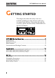
GPT-9600 Series User Manual GETTING STARTED This chapter describes the safety tester in a nutshell, including its main features and front / rear panel introduction. After going through the overview, please read the safety considerations in the Set Up chapter. AC / DC Withstanding Voltage / GPT-9603 Insulation Resistance Tester PASS FAIL ESC FIELD READY CAUTION HIGH VOLTAGE START TEST 5.0 kVAC MAX. 6.0 kVDC MAX. STOP RETURN REMOTE POWER EDIT SAVE UTILITY GPT-9600 Series Overview ..........
GETTING STARTED GPT-9600 Series Overview Series lineup The GPT-9600 Series Safety Testers are AC/DC withstanding voltage and insulation resistance safety testers. The GPT-9603 is an AC/DC withstanding and insulation resistance safety tester. The GPT-9602 is an AC/DC withstanding safety tester. The GPT-9612 is an AC withstanding and insulation resistance safety tester. The GPT-9601 is purely an AC withstanding safety tester.
GPT-9600 Series User Manual Features Interface Timer control Safety discharge Over temperature, voltage and current protection Pass, Fail, Test, High Voltage and Ready indicators PWM output (increased reliability) Interlock (configurable) Remote control start/stop interface terminal Signal I/O port for pass/fail/test monitoring and start/stop control/interlock Accessories and Package Contents Check the package contents to make sure all accessories and optional items are inc
GETTING STARTED GRA-417 Note Rack adapter panel (19”, 4U) Keep the packaging, including the box, polystyrene foam and plastic envelopes should the need arise to return the unit to GW Instek.
GPT-9600 Series User Manual Appearance GPT-9603/9602/9612/9601 Front Panel Display PASS/FAIL indicators Function keys Navigation keys AC / DC Withstanding Voltage / GPT-9603 Insulation Resistance Tester PASS FAIL ESC FIELD READY CAUTION HIGH VOLTAGE START READY indicator TEST HIGH VOLTAGE indicator STOP RETURN REMOTE POWER POWER button EDIT SAVE TEST indicator 5.0 kVAC MAX. 6.0 kVDC MAX.
GETTING STARTED The directional arrow keys are only used for calibration. They are not used during normal operation by the operator. The directional arrow keys can essentially be ignored by the operator. Directional arrow keys READY indicator READY The READY indicator is lit when the tester is ready to begin testing. TEST indicator TEST The TEST indicator is lit when a test is on. The START button is used to put the tester into TEST status from READY status.
GPT-9600 Series User Manual RETURN terminal RETURN The scroll wheel is used to edit parameter values or menu settings. Scroll wheel UTILITY key The RETURN terminal is used for IR, DCW and ACW tests. UTILITY Used to enter the TEST Utility or Common Utility menu. EDIT key EDIT Used to enter the EDIT status. The EDIT status allows you to select the test mode and the test parameters. SAVE key SAVE The SAVE key is used to save test parameters when in the EDIT status or to save utility settings.
GETTING STARTED START button START The START button is used to start tests. The START button can be used to start tests when the tester is in the READY status. Pressing the START button will put the tester in the TEST status. POWER switch POWER Turns the power on. The safety tester will always start up with the last test setting from when the instrument was last powered down.
GPT-9600 Series User Manual GPT-9603/9602/9612/9601 Rear Panel Calibration port Fan GND WARNING TO AVOID ELECTRIC SHOCK THE POWER CORD PROTECTIVE GROUNDING CONDUCTOR MUST BE CONNECTED TO GROUND. FOR CONTINUED FIRE PROTECTION. REPLACE ONLY WITH SPECIFIED TYPE AND RATED FUSE. NO OPERATOR SERVICEABLE COMPONENTS INSIDE. DO NOT REMOVE COVERS. REFER SERVICING TO QUALIFIED PERSONNEL. CALIBRATION USE ONLY ENSURE THE POWER IS REMOVED FROM THE INSTRUMENT BEFORE REPLACING THE FUSE SER. NO. LB POWER MAX.
GETTING STARTED Line voltage input and fuse holder Line voltage input: 100-120/220-240VAC Line Voltage Fuse: T 4A 250V 17
GPT-9600 Series User Manual Set Up Power Up Background Steps The GPT-9600 accepts line voltages of 100-120V and 220-240V at 50Hz or 60Hz. 1. Connect the power cord to the AC voltage input. 2. If the power cord does not have an earth ground, ensure the ground terminal is connected to an earth ground. Warning GND Ensure the power cord is connected to an earth ground. Failure could be harmful to the operator and instrument. 3. Press the Power button. POWER 4.
GETTING STARTED S Y S T EM S E S y s t em Ch e Ha r dwa r e C F i r mw a r e C L c h h F TES k i ng . e c k i n e c k i n T . . g . . . g T T T T I I I I ME R = ME R = ME R = ME R = 0 0 0 0 0 0 0 0 After the System Self Test completes, the tester will go into READY status and be ready to operate. READY Status H = 2 2 . 0mA 1 00 A CW L = 0 .
GPT-9600 Series User Manual Workplace Precautions Background WARNING The GPT-9600 Series are a high voltage instruments that output dangerous voltages. The following section describes precautions and procedures that must be followed to ensure a safe work environment. The GPT-96XX generates voltages in excess of 5kVAC or 6kVDC. Follow all safety precautions, warnings and directions given in the following section when using the instrument. 1.
GETTING STARTED Operating Precautions Background WARNING The GPT-9600 Series are high voltage instruments that output dangerous voltages. The following section describes precautions and procedures that must be followed to ensure that the testers are operated in a safe manner. The GPT-96XX generates voltages of up to 5kVAC or 6kVDC. Follow all safety precautions, warnings and directions given in the following section when using the instrument. 1.
GPT-9600 Series User Manual 6. Only connect the test leads to the HIGH VOLTAGE terminals before the start of a test. Keep the test leads disconnected at all other times. 7. Always press the STOP button when pausing testing. 8. Do not leave the safety tester unattended. Always turn the power off when leaving the testing area. 9. When remotely controlling the safety tester, ensure adequate safety measures are in place to prevent: Inadvertent output of the test voltage.
GETTING STARTED Basic Safety Checks Background The GPT-9600 Series are high voltage devices and as such, daily safety checks should be made to ensure safe operation. 1. Ensure all test leads are not broken and are free from defects such as cracks or splitting. 2. Ensure the safety tester is always connected to an earth ground. 3.
GPT-9600 Series User Manual OPERATION Menu Tree ....................................................................... 25 Menu Tree Overview ...............................................................................26 Test Lead Connection ...................................................... 29 ACW, DCW, IR Connection....................................................................29 ACW and DCW Grounding Mode Information ..................................30 IR Grounding Mode Information........
OPERATION Menu Tree This section describes the overall structure of the operation statuses and modes for the GPT-9600 safety testers. The testers have 6 operation statuses (EDIT, READY, TEST, STOP, PASS and FAIL).
GPT-9600 Series User Manual Menu Tree Overview READY status When the tester is in READY status, it is ready to begin testing. Pressing the START button will begin testing and put the tester into TEST status. Pressing the EDIT key will put the tester into the EDIT status. Pressing the UTILIY key will enter the Common Utility settings. READY Status H = 2 2 . 0mA 1 00 A CW EDIT status L = 0 . 0 0mA kV D CW T=174S mA I R READY MO D E T I ME EDIT status is used to edit the test parameters.
OPERATION TEST status TEST status is active when a test is running. Pressing STOP will cancel the test and put the tester into the STOP status. Waiting for the test to complete will result in a PASS or FAIL judgment. TEST Status H = 2 2 . 0mA 0 14 A CW STOP status kV D CW L = 0 . 0 0mA T=008S 0 00 mA I R TEST MO D E T I ME STOP status is shown when a test did not finish running and has been stopped by the operator. Pressing STOP will return the tester to READY status. STOP Status H = 2 2 .
GPT-9600 Series User Manual PASS Status When a DUT passes a test, the PASS status is displayed. Pressing STOP returns the unit to the READY status, pressing START will re-run the test again. PASS Status H = 2 2 . 0mA 0 90 A CW Common Utility Settings kV D CW L = 0 . 0 0mA T=060S 0 00 mA I R L CD CTRL T I ME T I ME R = T I ME R = R= T I ME R = 0 0 0 0 0 0 0 0 The TEST Utility configures the ARC mode (ACW, DCW) and the ACW test frequency.
OPERATION Test Lead Connection This section describes how to connect the GPT-9600 to a DUT for withstanding or insulation resistance tests. ACW, DCW, IR Connection Background ACW, DCW, IR Connection ACW, DCW and IR tests use the HIGH VOLTAGE terminal and RETURN terminal with the GHT-114 test leads. GPT-9000 High Voltage terminal DUT Return terminal Steps 1. Turn the power off on the safety tester. 2. Connect the high voltage test lead(red) to the HIGH VOLTAGE terminal and screw firmly into place. 3.
GPT-9600 Series User Manual ACW and DCW Grounding Mode Information Background For ACW and DCW tests, the GROUND MODE is always set to ON. In the ON setting, the GPT9600 grounds the return terminal to the ground. This mode is best for DUTs that are grounded to an earth ground by their chassis, fixtures or operation environment. This mode measures the potential of the HIGH VOLTAGE terminal with respect to earth ground.
OPERATION IR Grounding Mode Information Background Warning Example For IR tests the GROUND MODE is always set to OFF. Here, the return terminal is floating with respect to the earth ground. This mode is for DUTs that are floating and not directly connected to an earth ground. In this mode any stray capacitance/resistance that leaks to the earth ground from the DUT side of the testing circuit and will not be measured.
GPT-9600 Series User Manual Ground Mode Icon for IR tests H= MΩ 0 10 A CW L = 0 0 0 1 MΩ kV D CW T =OF F MΩ I R READY MO D E Ground mode OFF 32
OPERATION ACW, DCW and IR Testing This section describes how to create, edit and run a single ACW, DCW or IR safety test. Each setting described in this chapter only applies to the selected test mode – For example the test time setting for an ACW test is different to the DCW and IR test time settings. Setting the Test Function→ from page 34. Editing the Test Settings → from page 34. Setting the Upper and Lower Limits → from page 35. Setting the Test Time (Timer) → from page 37.
GPT-9600 Series User Manual Setting the Test Function There are three test functions, AC Withstand, DC Withstand and Insulation Resistance. Background Steps 1. To choose the test function, press the ACW, DCW or IR soft-keys when the tester is in the READY or EDIT status. A CW D CW I R 2. The test function soft-key is highlighted. H = 2 2 . 0mA 1 00 A CW L = 0 .
OPERATION READY H = 2 2 . 0mA 1 00 A CW L = 0 . 0 0mA kV T=174S mA D CW I R ED I T MO D E T I ME 2. The Status changes from READY to EDIT. Note Pressing the SAVE key will save the settings for the current test function and return back to READY status. Setting the Upper and Lower Limits Background Steps There is both L (low) and H (high) judgment settings. When the measured value is below the L setting, the test will be judged as FAIL.
GPT-9600 Series User Manual 0.01mA~22.0mA 0.01mA~6.00mA 0002MΩ~∞Ω ACW (H) DCW (H) IR (H) 3. Press the FIELD soft-key to bring the cursor to the L setting or the H setting. FIELD cursor H = 2 2 . 0mA 1 00 A CW L = 0 . 0 0mA kV D CW T=174S mA I R ED I T MO D E T I ME 4. Use the scroll wheel to set the H/L limit*. ACW (L) DCW (L) IR (L) Note 0.00mA~21.9mA 0.00mA~5.99mA 0001MΩ ~ 2000MΩ The L limit cannot be greater than the H limit.
OPERATION Setting the Test Time (Timer) Background The TIMER setting is used to set the test time for the test. The test time determines how long to run the test at the test voltage. This test time does not include the Ramp up time (fixed at 100ms) or initial start time. The test time can be set from 001 seconds to 180 seconds for ACW, DCW and IR tests, with a resolution of 1 second for all modes. The timer can also be turned off. The total discharge time depends on the DUT and is not specified.
GPT-9600 Series User Manual Note *Note that the T value cannot be edited with the scroll wheel if it is set to OFF. See below to toggle the test time on or off. When the output current exceeds 15mA, AC withstanding tests cannot be continuously performed without a cool down period between tests. For 15mA≤I≤20mA, the cool down period must equal or exceed the test time. See the AC Withstanding specifications on page 71 for details. Turning the test time off.
OPERATION Setting the ARC Mode Background ARC detection, otherwise known as flashover detection, detects fast voltage or current transients that are not normally detected. Arcing is usually an indicator of poor withstanding insulation, electrode gaps or other insulating problems that cause temporary spikes in current or voltage during ACW. There are three ARC detection settings: OFF, ON AND CONTINUE, ON AND STOP.
GPT-9600 Series User Manual 3. Use the scroll wheel to set the ARC mode. ARC MODES: OFF, ON AND CONTINUE, ON AND STOP 4. Press the SAVE key to save and exit the TEST Utility and go back to EDIT status. Note SAVE The ESC key can be pressed at any time in the Utility menu to cancel and exit. 5. If the ARC MODE was set to either ON AND CONTINUE, or ON AND STOP, the ARC current level will now appear on the display and can be edited. 6. Use the FIELD key to move the cursor to the ARC setting. 7.
OPERATION Saving and Exiting EDIT Status Background Steps After all test parameters have been set, the test can be saved. 1. When in EDIT status, press the SAVE key to save the test. SAVE ED I T H= MΩ 0 50 A CW L = 0 0 0 1 MΩ kV D CW T =OF F MΩ I R READY AC - I R 2. The Status changes from EDIT to READY. Note Pressing the SAVE key again will return the tester back to EDIT status for the current test.
GPT-9600 Series User Manual Setting the Test Voltage and Running a Test Background Note The test voltage can be set when the tester is in the READY status. After the test voltage has been set, the test can then be run. The tester cannot start to run a test under the following conditions: The INTERLOCK function is ON and the Interlock key is not inserted in the signal I/O port (page 56). The STOP signal has been received remotely.
OPERATION 4. For ACW and DCW tests, turn the scroll wheel to set the desired test voltage. 0.1kV ~ 5.0kV(ACV)/6.0kV(DCV) Range 5. For IR tests, turn the scroll wheel to set the voltage to one of five settings. 50V, 100V, 250V, 500V, 1000V Range Voltage setting H = 2 2 . 0mA 1 00 A CW L = 0 . 0 0mA kV D CW T=174S mA I R READY MO D E T I ME START 6. Press the START button. The test starts automatically and the tester goes into the TEST status. 7.
GPT-9600 Series User Manual Example Measured current TEST voltage TEST Status H = 2 2 . 0mA 0 94 A CW L = 0 . 0 0mA kV D CW T=008S 9 00 mA I R TEST MO D E T I ME Remaining test time Stop the Test STOP 9. To stop the test at any time when it is running, press the STOP button. The test will stop immediately. When the STOP button is pressed, a judgment is not made on the test. All panel keys except the STOP button are locked when the tester is in STOP status. Example STOP Status H = 2 2 .
OPERATION PASS / FAIL Test Judgments Background Note If the test is allowed to run to completion (the test is not stopped or a protection setting is not tripped) then the tester will judge the test as either PASS or FAIL. The test will be judged PASS when: The H and L limits (high and low limits) have not been tripped during the test time. The test will be judged FAIL when: Either the H or L limit has been tripped during the test time.
GPT-9600 Series User Manual Pressing the START button will restart the test again. PASS Timing Diagrams ACW PASS Timing START The timing diagrams below show the ACW, DCW and IR timing for the START status, TEST status and PASS judgment.
OPERATION FAIL Judgment 1. When the test is judged as FAIL, FAIL will be displayed, the buzzer will sound and the FAIL indicator will be lit red. FAIL As soon as a test is judged FAIL, the output is cut from the terminals. H = 2 2 . 0mA 1 00 A CW kV D CW L = 0 . 0 0mA T=060S 23 0 mA I R FA I L MO D E T I ME STOP 2. The FAIL judgment will be held on the display until the STOP button is pressed twice.
GPT-9600 Series User Manual DCW FAIL Timing START TEST FAIL Output V time TEST TIME RAMP (100ms) Discharge time IR FAIL Timing START TEST FAIL Output V time TEST TIME RAMP (100ms) 48 Discharge time
OPERATION Auto Mode Testing Background Steps The Auto Mode function allows you to run two test functions back to back automatically. Only after both tests have run will a PASS/FAIL judgment be determined on the tests. 1. Connect the DUT to the tester. Page 29 From Page 2. Ensure the tester is in READY 33 status and that all the testing parameters have been set for both the tests* that you wish to run in Auto Mode. 3. Press the Mode key to toggle between each of the Auto Modes.
GPT-9600 Series User Manual START 5. With the tester in READY status, press the START button. The test starts the first test and goes into the TEST status for the first test. 6. The TEST indicator will be lit orange when in the TEST status. TEST 7. The first test will start by showing the remaining test time. 8. For ACW or DCW tests, the scroll wheel can be used to edit the test voltage when the tester is in the TEST status. ACW 0.10kV ~ 5.0kV DCW 0.10kV ~ 6.0kV 9.
OPERATION Example Measured current TEST voltage TEST Status H = 2 2 . 0mA 0 94 A CW L = 0 . 0 0mA kV D CW 9 00 mA I R Currently running test Stop the Test T=008S TEST AC - I R Selected Auto Mode T I ME Remaining test time STOP 10. To stop the tests at any time when they are running, press the STOP button. Testing will stop immediately. When the STOP button is pressed, a judgment is not made on the current test. If a test has already been run, its judgment is still valid.
GPT-9600 Series User Manual PASS / FAIL Test Judgments for Auto Mode Background Note The test results for the Auto Mode testing are identical as the results from a single test, however: If one of the tests fails, then the FAIL judgment for that test will be shown on the display, even if the other test is judged as PASS. Only one test result can be viewed at any one time. A test will be judged PASS when: The H and L limits (high and low limits) have not been tripped during the test time.
OPERATION 3. The PASS judgment will be held on the display until the STOP or START button is pressed. STOP Pressing the STOP button will return the tester to the READY status. START Pressing the START button will restart the tests again. FAIL Judgment 4. After both tests have finished, if any or both of the tests are judged as FAIL, the output will be cut from the terminals, FAIL will be displayed on the screen, the buzzer will sound and the FAIL indicator will be lit red. H = 2 2 .
GPT-9600 Series User Manual 6. Turn the scroll wheel left to view the first test result and turn the scroll wheel back to the right to view the last test result again. STOP 7. Pressing the STOP button again will return the tester to the READY status. H = 2 2 . 0mA 1 00 A CW Timing Diagrams 54 L = 0 . 0 0mA kV D CW T=174S mA I R READY AC - I R T I ME The PASS/FAIL timing diagrams for the Auto Mode are same as those for single tests. See page 45 for PASS/FAIL judgments and timing diagrams.
OPERATION Common Utility Settings The Common Utility settings are system-wide settings that apply to all function tests. The Common Utility menu includes the following settings: LCD settings → from page 55. Control settings → from page 56. LCD Settings Description Steps The LCD settings include contrast and brightness controls. 1. Ensure the tester is in READY status. H = 2 2 . 0mA 1 00 A CW L = 0 . 0 0mA kV D CW T=174S mA I R READY MO D E 2. Press the UTILITY key. UTILITY 3.
GPT-9600 Series User Manual 5. Use the scroll wheel to select a parameter for the chosen menu item. LCD Contrast LCD Brightness 1(low) ~ 8(high) BRIGHT, DARK 6. Press SAVE to save the settings and exit to READY status. Note SAVE The ESC key can be pressed at any time to cancel and exit back to READY status. Control Settings Description The Control settings are accessed in the Common Utility menu. The Control settings include: Start Control, Double Action, Key Lock and Interlock.
OPERATION The Interlock function is a safety feature. The interlock function prevents a test from running, unless the interlock pins on the signal I/O port connector are shorted. The included interlock key can be used for this purpose. See page 65 for details. Steps 1. Ensure the tester is in READY status. H = 2 2 . 0mA 1 00 A CW L = 0 . 0 0mA kV D CW T=174S mA I R READY MO D E 2. Press the UTILITY key. 3. Press the CTRL soft-key to bring up the Control Common Utility menu.
GPT-9600 Series User Manual 6. Press SAVE to save the settings and exit to READY status. Note SAVE If a test is started with INTERLOCK ON, but the interlock signal I/O pins are not shorted (either with the included interlock key or manually), the INTERLOCK OPEN message will be displayed, preventing the test from starting. Interlock open message H = 6 . 0 0mA 0 00 A CW 58 L = 0 . 0 0mA I N T ER L OCK kV D CW I R = 1 .
EXTERNAL CONTROL EXTERNAL CONTROL The External Control chapter covers the REMOTE terminal and the SIGNAL I/O port. External Control Overview ............................................... 60 Remote Terminal Overview ................................................................... 60 Remote Controller Operation ................................................................ 61 SIGNAL I/O Overview ..........................................................................
GPT-9600 Series User Manual External Control Overview The External Control section describes the front panel REMOTE terminal connection and the rear panel SIGNAL I/O port. Remote Terminal Overview Overview WARNING Pin Assignment and Connection The REMOTE terminal connector is a standard 5-pin DIN terminal suitable for a remote controller. Keep any cables that are connected to the REMOTE terminal away from the HIGH VOLTAGE and RETURN terminals.
EXTERNAL CONTROL Remote Controller Operation Description The GPT-9600 accepts external remote controllers with a START and STOP button. To use the REMOTE terminal, the GPT-9600 must first be configured to accept a remote controller. Operating a remote controller is the same as operating the START and STOP buttons on the front panel. Steps 1. Insert the lead of remote controller into the REMOTE terminal. 2. Configure the Start Ctrl option to REMOTE CONNECT in the Common Utility menu.
GPT-9600 Series User Manual SIGNAL I/O Overview The SIGNAL I/O port can be used to remotely start/stop tests and monitor the test status of the instrument. The SIGNAL I/O port is also used for the interlock function (page 56). Overview The SIGNAL I/O port uses a DB-9 pin female connector.
EXTERNAL CONTROL Output Connection PIN 6 OUTPUT_TEST PIN 7 OUTPUT_FAIL PIN 8 OUTPUT_PASS PIN 9 OUTPUT_COM Signal Properties Input Signals High level input voltage Low level input voltage Low level input current Input period Output Signals Output Type Output Rated Voltage Maximum output current 5V ~ 32V 0V ~ 1V Maximum of -5mA Minimum of 1ms Relay form A 30VDC 0.
GPT-9600 Series User Manual Using the SIGNAL I/O to Start/Stop Tests Background Panel operation To use the SIGNAL I/O port the Start Ctrl settings have to be set to SIGNAL I/O in the Common Utility menu. 1. Set the Start Ctrl option to SIGNAL Page 56 I/O. 2. Connect the Input/Output signals to the SIGNAL I/O port. 3. To start the testing, short the INPUT_STOP and INPUT_COM line for a minimum of 1ms to put the tester into READY status. 4.
EXTERNAL CONTROL Using the Interlock Key Background Panel operation When the INTERLOCK function is set to ON, tests are only allowed to start when both Interlock pins on the signal I/O port are shorted. Using the Interlock key will short the INTERLOCK1 and INTERLOCK2 pins on the signal I/O port. See page 62 for the Signal I/O pin assignment. 1. Insert the Interlock key into the SIGNAL I/O port on the rear panel. 2. Set the INTERLOCK option to ON Page 56 in the Common Utility.
GPT-9600 Series User Manual FAQ • The tester will not turn on. • The panel keys are not working. • When I press the START button the tester will not start testing. • The accuracy does not match the specification. The tester will not turn on. Ensure the power cord is connected. Check to make sure the fuse is not blown. See page 68. The panel keys are not working. Ensure the tester is not in SIGNAL I/O or Remote Connect mode, page 56.
FAQ If “Interlock” is enabled, the interlock key must be inserted into the signal I/O port on the rear panel before a test can be started. See page 65 for details. Lastly, ensure that the Start Ctrl setting is correctly configured in the Common Utility menu. For example, to enable the START button to start a test, ensure that the Start Ctrl setting is set to FRONT PANEL. See page 56 for details. The accuracy does not match the specification.
GPT-9600 Series User Manual APPENDIX Fuse Replacement Steps 1. Turn the instrument off. 2. Remove the fuse socket using a flat screwdriver. 3. Replace the fuse in the fuse holder.
APPENDIX Error Messages Test Errors The following error messages or messages may appear on the GPT-9600 screen when configuring or running tests. Error Messages I ERR SHORT V ERR R ERR TIME ERR OVER 25W Description For ACW, DCW tests. Shown when the current is set too high. Voltage is too low. Indicates that the DUT could be shorted. For ACW, DCW and IR tests. Indicates that the voltage is too high. For IR tests. Resistance=0Ω. Check to see whether the DUT or test lead is shorting. For ACW tests.
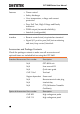
GPT-9600 Series User Manual GPT-9600 Specifications The specifications apply when the GPT-9600 is powered on for at least 30 minutes at 15˚C~35˚C. Specifications Environment Range Warranty Operation Storage Installation Location AC Withstanding Voltage Output Voltage Range Output Voltage Resolution Maximum Rated Load Maximum Rated Current Temperature Humidity ≤70% (No condensation) 15˚C ~ 35˚C ≤70% (No condensation) 0˚C ~ 40˚C ≤85% (No condensation) -10˚C ~ 70˚C Indoors at an amplitude of up to 2000m.
APPENDIX Output Limitation for Upper Current Withstanding Voltage Testing 15mA≤I≤20mA 0.01mA≤I<15mA Pause At least as long as the output time Not necessary Output Time Maximum 180 seconds Continuous output possible DC Withstanding Voltage Output Voltage Range Output Voltage Resolution Maximum Rated Load Maximum Rated Current 0.10kV~ 6.00kV 10V 25W (5kV/5mA) 6mA 0.01mA ~ 2mA (0.1kV≤V≤0.5kV) 0.01mA ~ 6mA (0.5kV
GPT-9600 Series User Manual Voltage Regulation Window Comparator Method RAMP (Ramp Time) TIMER (Test Time) GND Output Impedance ±1.5% + 2 counts [Maximum rated load → no load] Yes 0.
APPENDIX GPT-9600 Dimensions 328.9 Tester ESC FIELD READY CAUTION HIGH VOLTAGE START TEST 5.0 kVAC MAX. 6.0 kVDC MAX. STOP RETURN REMOTE POWER EDIT 322.0 SAVE 148.2 Insulation Resistance FAIL 134.0 AC / DC Withstanding Voltage / GPT-9603 PASS UTILITY 385.
GPT-9600 Series User Manual Declaration of Conformity We GOOD WILL INSTRUMENT CO., LTD. No. 7-1, Jhongsing Rd, Tucheng Dist., New Taipei City 236, Taiwan GOOD WILL INSTRUMENT (SUZHOU) CO., LTD. No. 69 Lushan Road, Suzhou New District Jiangsu, China.
INDEX INDEX Accessories ................................. 10 Auto mode test results ...................................... 52 Auto mode testing ..................... 49 Caution symbol ............................ 4 Cleaning the instrument ............. 6 Declaration of conformity ......... 74 Dimensions ................................. 73 Disposal instructions ................... 6 EN61010 measurement category .................. 5 pollution degree..............................