
User Manual

GETTING STARTED
25
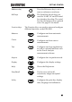
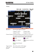
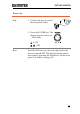
Display
Waveforms
Shows input signal waveforms.
Channel 1: Yellow Channel 2: Blue
Channel 3: Pink Channel 4: Green
Channel Indicator
The channel indicator shows the zero volt level of
the signal waveform for each activated channel.
The active channel is shown with a solid color.
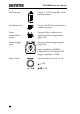
Math Bus (B1)
Active channel
(CH3)
Reference waveform
(Ref1)
Activated channel
(CH4)
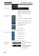
Trigger position
Shows the position of the trigger.
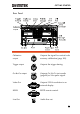
Horizontal
position
Shows the horizontal position.