
Instruction Manual
GDS-2000A
49
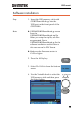
Note
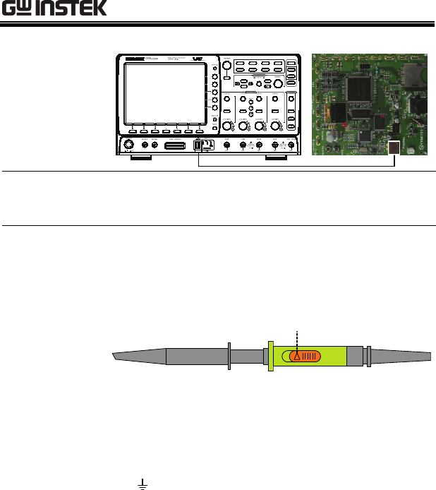
Make sure the power LED on the demo board
turns on.
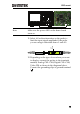
11. Select x10 as the attenuation on the probe to
limit the input signal amplitude if the probe
you are using is selectable from x1 and x10.
x10
x1
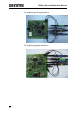
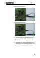
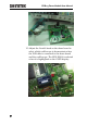
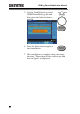
12. Depending on the type of waveform you want
to display, connect the probes to the terminals
marked, Analog CH1~CH4, Digital CH1~CH4,
Video, FM as shown in the diagrams below.
Connect the grounding clips to ground terminal
(
).