
User Manual

GDS-3000 Serial Decode User Manual
24
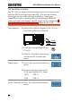
33. Press Event Table from the side
menu to toggle the event table On
or Off.
Event
On, Off
34. To save the event table, press Save
Event Table.
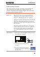
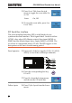
SPI Serial Bus Interface
The serial peripheral interface (SPI) is a full duplex 4 wire
synchronous serial interface. The 4 signals lines: Serial clock line
(SCLK), slave select (SS), Master output/slave input (MOSI, or
SIMO) and the Master input/slave output (MISO, or SOMI). The
word size is configurable from 8~32 bits. The SPI triggers on the
data pattern at the start of each framing period.
Panel operation
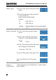
35. Insert each of the bus signals (SCLK, SS, MOSI,
MISO) to one of the oscilloscope channels.
GDS-3354
MOSI
MISO
X
1
0
X
1
X
1
0
X
1
SCLK
SS
X
1
0
X
1
X
1
0
X
1
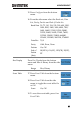
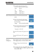
36. Press the corresponding bus key,
B1 or B2.
37. Press Bus from the bottom menu
and choose the SPI serial bus.
Define Inputs
38. Press Define Inputs from the lower
menu.