
Brochure

Setting Resolution
Accuracy
*2
200 V
100 V
200 V
Resolution
Accuracy
*2
Resolution
Accuracy
Resolution
Accuracy
*3
Resolution
Accuracy
*4
Resolution
Accuracy
*5
100 V
Setting Resolution
Accuracy
Stability
*5
DC OFFSET*
6
Accuracy
*2
200 V
200 V
-250 V to +250 V / -500 V to +500 V
±0.2% or less
0.15% @45 - 65Hz; 0.5% @DC, all other frequencies (0 to 100%, via output terminal)
0.7 Vrms / 1.4 Vrms (TYP)
0.5 % or less
100 us (TYP)
70 % or more
0.1 V
For 45 Hz to 65 Hz and DC: ±(0.5 % of reading + 0.3 V/0.6 V)For 40 Hz to 999.9 Hz: ±(0.7 % of reading + 0.9 V/1.8 V)
0.1 V
For 45 Hz to 65 Hz and DC: ±(|2 % of reading| + 1 V / 2 V)
0.01 A 0.01 A
For 45 Hz to 65 Hz and DC:±(0.5 % of reading+0.02 A/0.02 A); For 45 Hz to 65 Hz and DC:±(0.5 % of reading+0.04 A/0.02 A);
For 40 Hz to 999.9 Hz:±(0.7 % of reading + 0.04 A / 0.04 A) For 40 Hz to 999.9 Hz:±(0.7 % of reading + 0.08 A / 0.04 A)
0.1 A 0.1 A
For 45 Hz to 65 Hz and DC:±(|2 % of reading|+0.2 A/0.1 A) For 45 Hz to 65 Hz and DC:±(|2 % of reading|+0.2 A/0.1 A)
0.1 / 1 W 0.1 / 1 W
±(2 % of reading + 0.5 W)
Resolution
Accuracy
*5*6
Resolution
Accuracy
*5*7
Range
Resolution
Range
Resolution
±(2 % of reading + 1 W)
0.1 / 1 VA 0.1 / 1 VA
±(2 % of reading + 0.5 VA) ±(2 % of reading + 1 VA)
0.1 / 1 VAR 0.1 / 1 VAR
±(2 % of reading + 0.5 VAR) ±(2 % of reading + 1 VAR)
0.000 to 1.000 0.000 to 1.000
0.001 0.001
0.00 to 50.00 0.00 to 50.00
0.01 0.01
0.1 V
±(|0.5 % of set| + 0.6 V / 1.2 V)
5 A
2.5 A
20 A
10 A
500 W
10 A
5 A
40 A
20 A
1000 W
100Vac
200Vac
100Vac
200Vac
Setting Resolution
100 Vac to 240 Vac
90 Vac to 264 Vac
Single phase, Two-wire
47 Hz to 63 Hz
0 VA or less80
0.95 (typ.)
0.90 (typ.)
A8
4A
100 Vac to 240 Vac
90 Vac to 264 Vac
Single phase, Two-wire
47 Hz to 63 Hz
1500 VA or less
0.95 (typ.)
0.90 (typ.)
15 A
7.5 A
NORMINAL INPUT VOLTAGE
INPUT VOLTAGE RANGE
PHASE
INPUT FREQUENCY RANGE
MAX. POWER CONSUMPTION
POWER FACTOR
*1
MAX. INPUT CURRENT
INPUT RATING (AC)
AC MODE OUTPUT RATINGS (AC rms)
OUTPUT RATING FOR DC MODE
OUTPUT VOLTAGE STABILITY
OUTPUT VOLTAGE WAVEFORM DISTORTION RATIO, OUTPUT VOLTAGE RESPONSE TIME, EFFICIENCY
MEASURED VALUE DISPLAY
*1 For an output voltage of 100 V/200 V (100V/200V range), maximum current, and a load power factor of 1..
0.0 V to 175.0 V / 0.0 V to 350.0 V
0.1 V
±(0.5 % of set + 0.6 V / 1.2 V)
Single phase, Two-wire
5 A
2.5 A
20 A
10 A
500 VA
AC Mode: 40.00 Hz to 999.9 Hz, AC+DC Mode: 1.00 Hz to 999.9 Hz
0.01 Hz (1.00 to 99.99 Hz), 0.1 Hz (100.0 to 999.9 Hz)
For 45 Hz to 65 Hz: 0.01% of set, For 40 Hz to 999.9 Hz: 0.02% of set
± 0.005%
0.0° to 359.9° variable (setting resolution 0.1°)
Within ± 20 mV (TYP)
*1. 100 V / 200 V range
*2. For an output voltage of 17.5 V to 175 V / 35 V to 350 V, sine wave, an output frequency of 45 Hz to 65 Hz, no load, DC voltage setting 0V (AC+DC mode) and 23°C ± 5°C
*3. For an output voltage of 1 V to 100 V / 2 V to 200 V, Limited by the power capacity when the output voltage is 100 V to 175 V / 200 V to 350 V.
*4. With respect to the capacitor-input rectifying load. Limited by the maximum current.
*5. For 45 Hz to 65 Hz, the rated output voltage, no load and the resistance load for the maximum current, and the operating temperature.
*6. In the case of the AC mode and output voltage setting to 0 V.
*1. 100 V / 200 V range
*2. For an output voltage of -250 V to -25 V, +25 V to +250 V / -500 V to -50 V, +50 V to +500 V, no load, AC volatge setting 0V (AC+DC mode) and 23 ± 5℃℃
*3. For an output voltage of 1.4 V to 100 V / 2.8 V to 200 V, Limited by the power capacity when the output voltage is 100 V to 250 V / 200 V to 500 V.
*4. Within 5 ms, Limited by the maximum current.
*1. Power source input voltage is 100 V, 120 V, or 230 V, no load, rated output.
*2. For an output voltage of 75 V to 175V/150V to 350V, a load power factor of 1, stepwise change from an output current of 0 A to maximum current(or its reverse), using the output terminal on the rear panel.
*3. For 5 Hz to 1 MHz components in DC mode using the output terminal on the rear panel.
*1. At an output voltage of 50 V to 175 V / 100 V to 350 V, a load power factor of 1, and in AC and AC+DC mode.
*2. For an output voltage of 100 V / 200 V, a load power factor of 1, with respect to stepwise change from an output current of 0 A to the maximum current (or its reverse); 10% ~ 90% of output voltage
*3. For AC mode, at an output voltage of 100 V / 200 V, maximum current, and load power factor of 1 and sine wave only.
VOLTAGE
Setting Range
*1
OUTPUT PHASE
OUTPUT ON PHASE
MAXIMUM CURRENT
*3
100 V
Setting Range
MAXIMUM PEAK CURRENT
*4
100 V
FREQUENCY
POWER CAPACITY
10 A
5 A
40 A
20 A
1000 VA
VOLTAGE
LINE REGULATION
*1
LOAD REGULATION
*2
RIPPLE NOISE
*3
OUTPUT VOLTAGE WAVEFORM DISTORTION RATIO
*1
OUTPUT VOLTAGE RESPONSE TIME
*2
EFFICIENCY
*3
VOLTAGE
CURRENT
POWER
LOAD POWER FACTOR
LOAD CREST FACTOR
RMS, AVG Value
*1
PEAK Value
RMS, AVG Value
PEAK Value
Active (W)
Apparent (VA)
Reactive (VAR)
MAXIMUM CURRENT
*3
MAXIMUM PEAK CURRENT
*4
POWER CAPACITY
Setting Range
*1
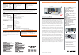
SPECIFICATIONS
ASR-2100/ASR-2100RASR 2050/ASR-2050R-
A.
C.
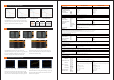
SEQUENCE MODE AND APPLICATIONS
OPERATING AREA FOR ASR-2000 SERIES
There are 10 sets of Sequence mode and each set has 0~999
steps. The time setting range of each step is 0.0001 ~ 999.9999
seconds. Users can combine multiple sets of steps to generate
The ASR-2000 series is an AC+DC power source that provides
rated power output not only at the AC output, but also at the DC
output. The operation areas are shown in diagrams.
B.
MEASUREMENT ITEMS FOR ASR-2000 SERIES
The ASR-2000 series provides users with measurement
capabilities including Vrms, Vavg, Vpeak, Irms, Iavg, Ipeak, IpkH,
P, S, Q, PF, CF, 40th-order Voltage Harmonic and Current
Harmonic. During the power output, the measurement
AC Output for
ASR-2050/ASR-2050R
DC Output for
ASR-2050/ASR-2050R
AC Output for
ASR-2100/ASR-2100R
DC Output for
ASR-2100/ASR-2100R
RMS Meas Display AVG Meas Display
Peak Meas Display
Voltage Harmonic Current Harmonic
ASR-2050
ASR-2100
ASR-2050R
ASR-2100R
500 VA
1000 VA
500 VA
1000 VA
5 / 2.5 A
10 / 5 A
5 / 2.5 A
10 / 5 A
350 Vrms / 500 Vdc
350 Vrms / 500 Vdc
350 Vrms / 500 Vdc
350 Vrms / 500 Vdc
Model Name
Power Rating
Max. Output Current
Max. Output Voltage
the desired waveforms, including waveform fallings, surges, sags,
changes and other abnormal power line conditions to meet the
needs of the test application.
parameters including Vrms/Irms, Vavg/Iavg and Vmax/Vmin/
Imax/Imin can be switched by users at any time to display the
instantaneous calculation reading.
Instantaneous Power Failure
Reset Behavior at Voltage DropMomentary Drop in Supply Voltage
Starting Profile Waveform