
User Manual User guide


APS-1102A User Manual
APS-1102A
9-2
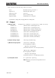
Unless otherwise noted, the following conditions are adopted:
Load: Resistance load of power factor 1
Output mode: INT (internal signal source)
Output waveform: Sine wave
Current Limiter: Factory default setting
Output terminals: Terminal block on rear panel
[set] indicates a setting value, and [rdg] indicates a reading value.
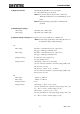
9.1 Output
a) Output mode All eight modes (combination of operation mode + signal source mode)
AC-INT mode (alternate current - internal signal source)
AC-EXT mode (alternate current - external signal source)
AC-ADD mode (alternate current - internal + external source)
AC-SYNC mode (alternate current - external synchronization)
AC+DC-INT mode (direct current - internal signal source)
AC+DC-EXT mode (direct current - external signal source)
AC+DC-ADD mode (direct current - internal + external source)
AC+DC-SYNC mode (direct current - external synchronization)
b) Output voltage ranges 100 V range and 200 V range
c) Maximum output power 750 VA (AC) / 750 W (DC)
Power supply input conditions:
100 V AC to 180 V AC input
(hereinafter referred to as “AC 100 V input system”)
1000 VA (AC) / 1000 W (DC)
Power supply input conditions:
180 V AC to 250 V AC input
(hereinafter referred to as “AC 200 V input system”)
d) Load power factor 0 to 1 (phase lead or phase lag)
Note: External power injection and regeneration are not
available.