
User Manual Manual


Figures
APS-1102 Programmable AC/DC Power Source ix
Figure 5-1. LCD Screen (When Normal) ....................................................................................... 5-3
Figure 5-2. LCD Screen (When Warning Is Displayed) ............................................................... 5-3
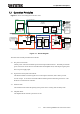
Figure 5-3. Menu Tree ................................................................................................................... 5-7
Figure 5-4. Modification Box ...................................................................................................... 5-13
Figure 5-5. Selection Box ........................................................................................................... 5-13
Figure 5-6. EXEC Box ................................................................................................................. 5-14
Figure 5-7. Block Diagram of Signal Sources ........................................................................... 5-17
Figure 6-1. Binary Block Data .................................................................................................... 6-10
Figure 6-2. Partial Command Tree .............................................................................................. 6-11
Figure 6-3. Command Tree ......................................................................................................... 6-42
Figure 6-4. Status System .......................................................................................................... 6-43
Figure 6-5. Standard Event Status Register .............................................................................. 6-45
Figure 6-6. Operation Status ...................................................................................................... 6-47
Figure 6-7. Warning Status ......................................................................................................... 6-48
Figure 7-1. Screen Display When Self Fault Check Errors Have Occurred ............................... 7-5
Figure 7-2. Screen Display When Protection Function-Related Error Has Occurred ................ 7-6
Figure 7-3. Screen Display When Panel Operation Error Has Occurred .................................... 7-8
Figure 7-4. Screen Display When Warning Has Occurred ......................................................... 7-11
Figure 8-1. Air Filter Cleaning Steps ........................................................................................... 8-3
Figure 8-2. SYSTEM INFORMATION Screen ................................................................................ 8-6
Figure 9-1. Temperature and Humidity Ranges ......................................................................... 9-15
Figure 9-2. External Dimensions ............................................................................................... 9-16