Programmable AC/DC Power Source APS-1102 CONTROL SOFTWARE USER MANUAL ISO-9001 CERTIFIED MANUFACTURER
Novemember 2009 This manual contains proprietary information, which is protected by copyrights. All rights are reserved. No part of this manual may be photocopied, reproduced or translated to another language without prior written consent of Good Will company. The information in this manual was correct at the time of printing. However, Good Will continues to improve products and reserves the rights to change specification, equipment, and maintenance procedures at any time without notice.
Preface Thank you for purchasing the APS-1102 Programmable AC/DC Power Source. To ensure safe use of this product, please first read Safety Precautions on the following pages. Before Reading This Manual This manual is a PDF file stored in the CD-ROM (filename: APS-1102 Control Software Manual.pdf which comes with the APS1102 Programmable AC/DC Power Source). Acrobat Reader (Adobe Systems, Inc.) Ver. 9 or higher is required to view the file contents.
Safety Precautions To ensure safe use, be sure to observe the following warnings and cautions. Good Will shall not be held liable for damages that arise from failure to observe these warnings and cautions. Be sure to observe the contents of this user manual. This user manual contains information for the safe operation and use of this product. Be sure to read this information first before using this product.
Disclaimer The APS-1102 Control Software (hereinafter, “this software”) was shipped after having undergone full testing and inspection by the Good Will company. Should this product fail due to a manufacturing flaw or due to a mishap during shipping, contact Good Will or a Good Will authorized distributor. Good Will Instek takes no responsibility for any damage caused by use of this software. In addition, we assume no obligation to modify the software or provide support if this software contains flaws.
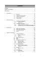
Contents Preface ............................................................................................ i Safety Precautions ........................................................................... ii Disclaimer ........................................................................................ iii 1. OVERVIEW ................................................................................. 1-1 1.1 1.2 1.3 1.4 1.5 General ...........................................................
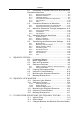
Contents 4.9 4.10 4.11 System Setup ................................................ 4-11 Errors ............................................................ 4-12 Restrictions in the Offline Mode ..................... 4-12 5. LOGGING .................................................................................. 5-1 5.1 5.1.1 5.1.2 5.1.3 5.2 5.3 5.4 5.5 5.6 5.7 5.8 Component Names .......................................... 5-2 Logging screen .......................................................
Contents 8.1 Generation of Standard Waveform and Numerical Expression Waveform ................................................ 8-2 8.1.1 8.1.2 8.1.3 8.1.4 8.1.5 8.1.6 8.2 Range setting and page ......................................... 8-3 Waveform selection ................................................ 8-3 Parameter setting ................................................... 8-4 Inter-Waveform Numerical Expression ................... 8-5 File operation ...............................................
Contents 11-3 11.4 11.5 11.6 11.7 11.8 Transfer Arbitrary Wave Data ........................ 11-4 Clear Arbitrary Waveform Memory ................. 11-6 Mode Setting ................................................. 11-6 System Settings ............................................ 11-7 List of Initial Setting Values ........................... 11-8 11.8.1 11.8.2 Initial values of set parameters ............................. 11-8 List of other parameter initial values ..................... 11-9 12.
Figures and Tables Page Figure Figure Figure Figure Figure Figure Figure Figure Figure Figure Figure Figure Figure Figure Figure Figure Figure Figure Figure Figure Figure Figure Figure Figure Figure Figure Figure Figure Figure Figure Figure Figure Figure Figure Figure Figure Figure Figure 3-1 Launcher ..................................................................................................................... 3-2 4-1 Remote Control Screen ...........................................................
Figures and Tables Figure Figure Figure Figure Figure Figure Figure Figure Figure Figure Figure Figure Figure 9-10 Message Display Area ...................................................................................... 9-15 10-1 Sequence View Window .................................................................................. 10-2 10-2 Select Display Area .......................................................................................... 10-4 10-3 Selecting Display Area ...................
1. 1.1 1.2 1.3 1.4 1.5 O VERVIEW General ........................................................... 1-2 Organization of Product ................................... 1-2 Software Configuration .................................... 1-3 Online/Offline .................................................. 1-3 Conventions ....................................................
APS-1102 Control Software Manual 1.1 General The APS-1102 Control Software is a program that supports remote control of the APS-1102 Programmable AC/DC Power Source, an arbitrary wave function and a sequence function. This software runs under the Windows 2000 and XP operating systems in a personal computer (PC), and controls transfer of control data, arbitrary waveform data, and sequence data on the APS-1102 Programmable AC/DC Power Source via a USB interface and execution of other operations.
1.3 Software Configuration 1.3 Software Configuration The APS-1102 Control Software consists of a launcher and subsoftware launched from the launcher. There are the following three types of subsoftware. Remote Control Software (abbreviated as RMT) Arbitrary Waveform Editor (abbreviated as ARB) Sequence Edit Software (abbreviated as SEQ) Caution Only one subsoftware application can be run from the launcher at a time.
2. 2.1 2.1.1 2.1.2 2.2 2.2.1 2.2.2 2.2.3 I NSTALLATION Hardware Requirements .................................. 2-2 Personal computer ................................................. 2-2 USB interface ......................................................... 2-2 Installation Procedure ..................................... 2-3 Installing the USB driver software .......................... 2-3 Installing the APS-1102 CONTROL SOFTWARE ....
APS-1102 Control Software Manual 2.1 Hardware Requirements Before installing the APS-1102 Control Softwarecheck that the system satisfies all the requirements below. 2.1.1 Personal computer CPU: 300 MHz or faster (1 GHz or faster recommended) Memory: 256 MB or more (512 MB or more recommended) Free hard disk space: 50 MB or more Display: 1024 × 768 pixels or higher and 256 colors or more.
2.2 Installation Procedure 2.2 Installation Procedure When installing or uninstalling the software in a Windows 2000 or XP environment, log on as a user who has an administrator privilege with a user name comprising 1-byte characters. 2.2.1 Installing the USB driver software The USB driver software can be downloaded from the National Instruments Corporation website. The procedures for installing the USB driver software are described below. 1.
APS-1102 Control Software Manual 2.2.2 Installing the APS-1102 CONTROL SOFTWARE (a) Insert the APS-1102 Control SoftwareCD-ROM into the CD-ROM drive of the PC. (b) Execute [Setup.EXE] on the CD-ROM or [D:\Setup.EXE] from [Run] on the start menu. [D:] indicates the CD-ROM drive. If another drive letter is assigned to the CD-ROM driver, assign it appropriately, according to your system. (c) Click the Next button, following the screen guidance to start installation.
3. 3.1 3.2 3.3 3.4 L AUNCHER Starting the Launcher ...................................... 3-2 Starting the Subsoftware ................................. 3-2 Exiting the Launcher ....................................... 3-3 Notes ..............................................................
APS-1102 Control Software Manual 3.1 Starting the Launcher Click [APS1102] from Start - [Programs] - [APS_TOOL] - [APS1102] to start the launcher. Remote control icon ARB icon SEQ icon Exit icon Figure 3-1 Launcher a) Remote control icon Starts the Remote Control Software. b) ARB icon Starts the Arbitrary Waveform Editor. c) SEQ icon Starts the Sequence Edit Software. d) Exit icon Exits the launcher. 3.
3.3 Exiting the Launcher 3.3 Exiting the Launcher The launcher is exited with the Exit icon or the Close button for the lancher. However, the launcher cannot be exited while the subsoftware is running. Exit the subsoftware before exiting the launcher. 3.4 Notes Settings for connected devices must be made on each subsoftware application. For details, see “System settings” or “Model settings” for each subsoftware. Remote Control See “4.9 System Setup”. Arbitrary Waveform Creation See “8.5.
4. R 4.1 4.1.1 4.1.2 4.1.3 4.2 4.3 4.4 4.5 4.5.1 4.5.2 4.5.3 4.5.4 4.6 4.6.1 4.6.2 4.6.3 4.7 4.7.1 4.7.2 4.8 4.8.1 4.8.2 4.9 4.10 4.11 EMOTE CONTROL Component Names .......................................... 4-2 Remote control screen ........................................... 4-2 Toolbar ................................................................... 4-3 Status bar ............................................................... 4-3 Menu Organization ..........................................
APS-1102 Control Software User Manual 4.1 Component Names When the RMT remote control (RMT) is started, the following remote control screen appears. 4.1.1 Remote control screen a) b) f) c) e) d) g) h) i) Figure 4-1 Remote Control Screen a) Menu organization See “4.2 Menu Organization”. b) Toolbar See “4.1.2 Toolbar”. c) Mode and range See “4.5.1 Mode and Range”. d) Oscillator settings See “4.5.2 Oscillator settings”. e) Misc settings See “4.5.3 Miscellaneous settings”. f) Output settings See “4.
4.1 Component Names g) Status monitoring See “4.8 Status Display”. h) Comment See “4.6.3 Comments”. i) Status bar See “4.1.3 Status bar”. 4.1.2 Toolbar Details for the toolbar on the remote control screen are shown below. Open icon Logging icon Save icon Store icon Recall icon Figure 4-2 Toolbar 4.1.3 Status bar Details for the status bar on the remote control screen are shown below.
APS-1102 Control Software User Manual 4.2 Menu Organization The menu organization of the “RMT Remote Control Software” is shown below. File (F) Open(O)* Ctrl+O Opens the device setting file. Save(S) Ctrl+S Saves data in the current device setting file. Save As(A) Saves data in the new device setting file. Exit(X) Exits this software. Store Displays the "Store Memory" dialog box. Recall Displays the "Recall Memory" dialog box. Reset Initializes the device to the factory settings.
4.4 Exit If a sequence is being executed or held on a device that can be connected at startup, the sequence is stopped and the software is started. If the device is in the online mode, the connected device is querried and the query results from the device for each setting item on the remote control screen are reflected to the screen. 4.4 Exit The software is exited when [File(F)] - [Exit(X)] is selected or when 4.5 (close box) is clicked.
APS-1102 Control Software User Manual 4.5.2 Oscillator settings Set each output setting item. Input a numerical value or select an item from the list and click the [SET] button. The item is then set to the device. Figure 4-7 Oscillator Settings (AC-INT mode) For a numerical setting input item, the setting range appears when the mouse pointer is moved to the input area. Figure 4-8 Setting Range Display Example The items that cannot be set in the current mode are disabled and cannot be changed.
4.5 Operations for Each Unit The limiters or range limit values under the miscellaneous settings can only be set to the device through the “RMT Remote Control Software”. Input checking for items corresponding to the “oscillator settings” is not performed. Like the “oscillator settings”, the setting range for the numerical setting input item is also displayed under the miscellaneous settings.
APS-1102 Control Software User Manual 4.6 Device Setting File The settings for each setting item that can be set with the “RMT Remote Control Software” (except for output on/off setting) can be saved to and read from the “device setting file”. The extension for the “device setting file” is “.MSF”. If the device is in the online status when the device setting file is read, the items are set to the device according to the device setting file to be read. 4.6.
4.7 Memory 4.7 Memory 4.7.1 Store and recall Store or recall the device in the online status. See the device manual for setting items saved during the storing or recalling operation. Figure 4-11 Store/Recall Memory Dialog Box a) Store Select [Memory] - [Store] or click the Store button to display the [Store Memory] dialog box. Set the memory number to be stored in [Memory No] in the [Store Memory] dialog box and click the OK button. Data is then stored in the device.
APS-1102 Control Software User Manual 4.8 4.8.1 Status Display Status monitor The status monitor querries the device for status information about every two seconds and refreshes the status display. The statuses to be monitored are listed below.
4.9 System Setup 4.9 System Setup When [Tool(T)] - [System Setup(S)] is selected, the [System Setup] dialog box appears. Figure 4-13 System Setup Dialog Box Model Select the model name of the device to be connected. (Only APS-1102 can be selected.) Interface Select the external interface of the device to be connected. (Only USBTMC can be selected.) Serial NO Input the serial number of the device to be connected. Set a 7-digit number in the APS-1102.
APS-1102 Control Software User Manual 4.10 Errors “RMT” checks for device errors when the device has been set in the online status. If an error occurs on the device, an error message appears. Figure 4-15 Error Message Example The error message displays the error number and details for the corresponding error. For details, see the device manual.
5. 5.1 5.1.1 5.1.2 5.1.3 5.2 5.3 5.4 5.5 5.6 5.7 5.8 L OGGING Component Names .......................................... 5-2 Logging screen ....................................................... 5-2 Toolbar ................................................................... 5-3 Status bar ............................................................... 5-3 Menu Organization .......................................... 5-3 Start and Termination ......................................
APS-1102 Control Software User Manual 5.1 Component Names The logging screen for the “RMT Remote Control Software” is shown below. 5.1.1 Logging screen a) b) c) d) Figure 5-1 Logging Screen a) Menu organization See “5.2 Menu Organization”. b) Toolbar See “5.1.2 Toolbar”. c) Data display area See “5.5 Data Display Area”. d) Status bar See “5.1.3 Status bar”.
5.2 Menu Organization 5.1.2 Toolbar The toolbar on the logging screen is detailed below. Start button Stop button Figure 5-2 Toolbar on Logging Screen 5.1.3 Status bar The status bar on the logging screen is detailed below. Offline or online Mo del name o f connecte d d evice Loggi ng start time Figure 5-3 Status Bar on Logging Screen Mode indicator The mode indicator displays “ON Line” or “OFF Line”. See “1.4 Online/Offline”. Connected device name Displays the connected device name.
APS-1102 Control Software User Manual 5.3 Start and Termination To display the logging screen, select [Logging] - [Logging] or click the Logging button on the remote control screen. See “4.2 Menu Organization”. See “4.1.2 Toolbar”. Clicking the Close button on the logging screen closes the logging screen regardless of the logging status. Exiting the remote control screen also closes the logging screen regardless of the logging status. 5.
5.6 Logging Conditions 5.6 Logging Conditions Select [Setting(S)] - [Logging Condition] to display the [Logging Condition] dialog box. Figure 5-4 Logging Condition Dialog Box Save in File When this check box is selected, currently logged data is saved to a file. Save Folder Specify the folder to which logging data is saved. To specify the destination folder, click the button to display the [Specify Folder] dialog box where the destination folder can be specified.
APS-1102 Control Software User Manual 5.8 Logging Data The following measurement values are logged depending on the device mode and measurement value display.
6. O VERVIEW OF ARBITRARY WAVEFORM CREATION 6.1 6.2 6.3 6.4 6.5 6.6 6.7 6.8 6.9 General ........................................................... 6-2 Start and Termination ...................................... 6-3 Standard Waveform ......................................... 6-3 Copying and Pasting a Waveform ................... 6-4 Numerical Expression Waveform ..................... 6-5 Waveform Generation Through Interpolation ... 6-6 Compression and Extension of Waveform - 1 ..
APS-1102 Control Software User Manual 6.1 General This chapter describes several examples so that you can understand basic operations and functions for the “ARB Arbitrary Waveform Editor” (ARB). It will be easier to understand the description if you read it while actually operating the software. The following conventions are used in this chapter. 6.3 Standard Waveform 6.4 Copying and Pasting a 6.5 Numerical Expression Waveform Waveform 6.6 Waveform Generation Through Interpolation 6.
6.2 Start and Termination 6.2 Start and Termination To start the “ARB Arbitrary Waveform Editor”, see “3.2 Starting the Subsoftware”. To exit the editor, click (close box) at the top right or execute [File] - [Exit]. The [Exit Program. Are you sure?] confirmation message appears in either case. Click the Yes(Y) button. In the following examples, operations are explained from the default status when the ARB Arbitrary Waveform Editor is started.
APS-1102 Control Software User Manual 6.4 Copying and Pasting a Waveform This section explains how to create a full-wave rectification waveform, as a sample of copying and pasting waveforms. Step 1: Click the button to the top left of the screen. The same result can be obtained when [Tools] - [Waveform Create] is selected. Step 2: The sine wave is selected in the initial status, so click the All Page OK button without changing it and return to the waveform display screen.
6.5 Numerical Expression Waveform 6.5 Numerical Expression Waveform This section explains how to create a waveform by superposing 3rd and 5th harmonics over the fundamental wave, as a sample of generating a waveform with a numerical expression. Step 1: Select [Setup] - [Setup]. The screen titled [ARB - System Settings] appears. Step 2: Click the [Unit Setup] page tab. Step 3: Click the button to the right of [X-Axis Unit] and click [User Unit] from the displayed list.
APS-1102 Control Software User Manual 6.6 Waveform Generation Through Interpolation This section explains how to create a smooth pulse waveform, as a sample of generating a waveform through interpolation. Step 1: Select [Setup] - [Setup] to display the dialog box titled [ARB - System Setup]. Next, click the [Unit Setup] page tab. Step 2: Click the button to the right of [X-Axis Unit] and click [User Unit] from the displayed list.
6.7 Compression and Extension of Waveform - 1 6.7 Compression and Extension of Waveform - 1 This section explains how to create a burst waveform by contracting the sine wave to the first quarter of the waveform display screen, as a sample of horizontally contracting/extending a waveform. Step 1: Click the button at the top left of the screen. A sine wave is selected in the initial status. Change the numerical value to the right of [Period] from [1] to [4] to make a sine wave with four cycles.
APS-1102 Control Software User Manual 6.8 Compression and Extension of Waveform - 2 This section explains how to create a trapezoidal wave by extending and clipping a triangle wave, as a sample of vertically contracting/extending a waveform. Step 1: Click the button at the top left of the screen. A sine wave is selected in the initial status. Click the button to the right of [Function], click [Triangle] from the displayed list. Click the All Page OK button to return to the waveform display screen.
6.9 Operation Between Waveforms setting [Transition] on a square wave. 6.9 Operation Between Waveforms This section explains how to create a waveform by superposing noise over a sine wave, as a sample of operation between waveforms. Step 1: Click the button at the left top of the screen. A sine wave is selected in the initial status. Change the numerical value to the right of [Function] from [65534] to [50000] to reduce the amplitude a little bit.
7. A RBITRARY WAVEFORM OPERATIONS ON WAVEFORM DISPLAY SCREEN 7.1 Organization and Functions of Waveform Display Screen ....................................................................... 7-2 7.2 Tool Menu ....................................................... 7-4 7.3 Setting Menu ................................................... 7-4 7.4 Undo and Redo ............................................... 7-4 7.5 Zooming and Scrolling the Display .................. 7-5 7.5.1 7.5.2 7.5.3 7.5.4 7.5.5 7.5.
APS-1102 Control Software User Manual The display that appears when the “ARB Arbitrary Waveform Editor” is started is called the waveform display screen. How to start: See “3.2 Starting the Subsoftware”. This chapter describes the functions and operations on the waveform display screen. 7.1 Organization and Functions of Waveform Display Screen “Figure 7-1 Waveform Display Screen ” shows the names of each component on the waveform display screen.
7.1 Organization and Functions of Waveform Display Screen The menu bar has a pull-down menu. Clicking a menu name displays the menu options. Clicking an option executes that function. Otherwise, pressing the Alt key and pressing the key for the underlined alphabetic character to the right of the menu name displays the options for the menu (for example, Alt , F displays the options for the [File] menu).
APS-1102 Control Software User Manual 7.2 Tool Menu The tool menu options are shown below. Opens the waveform create screen, as does the button on the toolbar. Opens the compress/decompress screen, as does the Opens the interpolate screen, as does the Opens the operate screen, as does the button on the toolbar. button on the toolbar. button on the toolbar. For example, pressing Alt , T , C opens the waveform generation screen. Waveform create screen See “8.
7.5 Zooming and Scrolling the Display 7.5 Zooming and Scrolling the Display 7.5.1 Vertical zoom The waveform display can be independently zoomed vertically or horizontally. The vertical magnification ratio can be [1:1] (display the whole waveform), [1:2] (display the half of waveform to the full screen), [1:4]... up to [1:256]. button to the right of [Zoom Vert] and select the desired item from the display Click the magnification ratio list.
APS-1102 Control Software User Manual 7.5.5 Marker operations a) Marker types There are two markers used in the ARB: marker A and marker B. Marker A cannot be set to the right of marker B. marker A must be always to the left of or at the same position as marker B. Marker A Marker B The position of each marker is displayed to the right of [MrkA(X)] and [MrkB(X)]. The waveform value to the marker position is displayed to the right of [A(Y)] and [B(Y)].
7.6 File Operations and Printing By setting a numerical value, it is possible to freely specify the marker position within the setting/display resolution range without being restricted by the waveform data address. d) Marker interlock mode When (option button) to the left of [ Indep] on the toolbar is selected ( ), markers A and B independently move. Clicking the option button to the left of [tRack] or pressing Alt + R interlocks marker A and marker B.
APS-1102 Control Software User Manual 7.6.1 File types ARB can read/write the following types of files. The text between parentheses is the file extension to be added to each file type. - Specialized format file containing waveform data, signal generator settings, and display unit See “7.6.3 Specialized format file”. settings (.wdb) See “7.6.4 Text file”. - Text file containing waveform data only (.
7.6 File Operations and Printing 7.6.4 Text file Waveform data created using the “ARB” can be also saved in a text file so that other applications can easily handle it. Selecting [File] - [Save As(TXT)] ( Alt , F , T or Ctrl + T ) displays the screen titled [Save As]. Saving location Input file name Select a saving location, input a file name and click the Save button. The file extension is “.txt” and can be omitted during file name input.
APS-1102 Control Software User Manual 7.6.5 Import Waveform data created using other software than the “ARB” can be imported as ARB’s waveform data. Selecting [File] - [Import(I)] ( Alt , F , I or Ctrl + I ) displays the screen titled [IMPORT]. File location File name input File type Select a file type in [Files of type]. Specify a file location, input a file name, and click the Open button.
7.7 Copy and Paste 7.6.6 Print Waveform data created using the “ARB” can also be printed out as a waveform. However, note that See “7.3 Setting Menu”. the grid is not printed out. Selecting [File] - [Print] ( Alt , F , P or Ctrl + P ) displays the screen titled [ARB - Print]. Make settings for the printer or font as needed and click the OK button. The upper, lower, and left margins cannot be set when printing the waveform. Margin setting is invalid when printing the waveform.
APS-1102 Control Software User Manual Data on the clipboard can be pasted as is to the text editor, spreadsheet software, or other application or pasted within that “ARB” or other “ARB” when multiple ARBs are operating. Cut The selected part is deleted. Clipboard The selected part remains the same. Clipboard Copy Selected range Paste When the clipboard data is smaller: 0 is embedded at the end. Paste When the clipboard data is larger: The overflowed section disappears.
8. A RBITRARY WAVEFORM OTHER SCREEN OPERATIONS 8.1 Generation of Standard Waveform and Numerical Expression Waveform ................................................ 8-2 8.1.1 8.1.2 8.1.3 8.1.4 8.1.5 8.1.6 8.2 8.2.1 8.2.2 8.3 8.3.1 8.3.2 8.3.3 8.4 8.4.1 8.4.2 8.4.3 8.5 8.5.1 8.5.2 8.5.3 8.5.4 8.5.5 8.5.6 8.5.7 8.5.8 Range setting and page ......................................... 8-3 Waveform selection ................................................ 8-3 Parameter setting .........................
APS-1102 Control Software User Manual This chapter describes the functions and operations on each screen other than the waveform display screen. How to start each screen “7.1 Organization and Functions of Waveform Display Screen” (toolbar description) “7.2 Tool Menu” 8.1 Generation of Standard Waveform and Numerical Expression Waveform The waveform generation screen is used to generate the standard waveform and numerical expression waveform.
8.1 Generation of Standard Waveform and Numerical Expression Waveform 8.1.1 Range setting and page On the waveform generation screen, it is required to specify the independent “range” and “waveform definition” for each page to create a waveform. (Range specification with the markers on the waveform display screen hardly effects the waveform generation screen.) Set the range for each page in the two numerical input areas to the right of [Range(X)].
APS-1102 Control Software User Manual 8.1.3 Parameter setting The parameters in “Table 8-1 Parameters for Standard Waveforms” can be set for sine waves, triangle waves, square waves, noise, and DC.
8.1 Generation of Standard Waveform and Numerical Expression Waveform 8.1.4 Inter-Waveform Numerical Expression Selecting [Waveform Function] in “8.1.2 Waveform selection” displays the constant input section [Constant] and numerical expression input section [Y=]. Figure 8-2 Waveform Generation Screen - Waveform Function Input the constant and expression and click the Compute button to check the calculated waveform in the waveform display on the waveform generation screen.
APS-1102 Control Software User Manual Constants must be strings other than those shown in “Table 8-4 Built-in Function”. It is recommended to use strings different from those in “Table 8-2 Built-in Constants”. When the All Page OK button is clicked, the constant takes effect on the page where the constant is defined and subsequent pages. For example, the constant defined on the first page affects all the pages.
8.1 Generation of Standard Waveform and Numerical Expression Waveform When the horizontal axis unit is [Time] and the cycle is 1 ms, the result of the expression will be 1e-3 = 2**0.0001591..., a value that barely changes around the 0 of sine wave. If the vertical axis unit is [User unit] and 0 to 1, the result of the expression will be 1 = 2**0.1591..., waveform of about one/sixth of the former half of sine wave.
APS-1102 Control Software User Manual e) Built-in functions The functions shown in “Table 8-4 Built-in Function” can be used in the numerical expression input section [Y=] in the “ARB”. The argument for the trigonometric function is a radian expression. Power() and phase() are functions that specify the real part in expression 1 and the imaginary part in expression 2 and return the size or declination of a complex vector.
8.1 Generation of Standard Waveform and Numerical Expression Waveform Page 1 [Constant] [None] [Y=] [((sin(x)>=0)-0.5)*2] (Obtain 0/+1 square wave using the logical operator “>=” and convert it to ±1.) DC sweep waveform (horizontal axis: user unit 0 to 1, vertical axis: user unit 1 to +1) Page 1 [Constant] [None] [Y=] [(x-0.5)+sin(2*pi*x*32)/2] Damped wave (horizontal axis: user unit 0 to 6.
APS-1102 Control Software User Manual [Constant] [j=50;] [Y=] [sin(s*x)+cos(s*j*x)/2+0.5] (Create a sine wave across page 1 and overwrite the surge waveform on page 2.) Sin(X)/X waveform (horizontal axis unit: address 0 to 2048, vertical axis unit: data ±32767) Page 1 [Range(X)] [0] to [2048] [Constant] [fs=32767;] [Y=] [fs*sin((x-s)/k)/((x-s)/k)] [s=2048;] [k=174;] Page 2 [Range(X)] [Constant] Page 3 [Range(X)] [Constant] 8.1.
8.2 Contraction/Extension of Waveform 8.2 Contraction/Extension of Waveform The contraction/extension screen is used to vertically or horizontally contract or extend the waveform in the selected range. Click the button on the tool menu or select [Tool] - [Compress/Decompress (P)] ( Alt , T , P ) to open the contraction/extension screen.
APS-1102 Control Software User Manual 8.2.1 Contraction/extension of horizontal axis Select the range with the markers on the waveform display screen before contracting/extending the “7.5.6 Range selection” horizontal axis. Contraction/extension of the horizontal axis can be set in the contraction/extension screen [X axis] area.
8.2 Contraction/Extension of Waveform 8.2.2 Contraction/extension of vertical axis The vertical axis is contracted/extended within the selected range. Select the range with the markers on the waveform display screen before contracting/extending the vertical axis. “7.5.6 Range selection” The contraction/extension of the vertical axis is set in the [Y Axis] area on the contraction/extension screen.
APS-1102 Control Software User Manual d) Miscellaneous When the setting results in extension that exceeds the ± full scale range, waveforms are clipped at the ±full scale range. Note that the waveform may be distorted when the rate is too high. 8.3 Waveform Generation Through Interpolation The interpolation editing screen is used to create waveforms with different types of interpolation. The “point” set for interpolation is called the “control point”.
8.3 Waveform Generation Through Interpolation 8.3.1 Control point setting Interpolation is applied to the range selected by markers on the waveform display screen. Although control points can be set outside the selected range, they will be ignored in the actual interpolation. a) Specifying the control point with a numerical value Input numerical values in the input areas to the right of [X=] and [Y=] on the interpolation editing screen.
APS-1102 Control Software User Manual f) Deleting all the control points Click the Delete All button to select all the set control points. The selected control points cannot be restored. Take extra care when using this function. 8.3.2 Interpolation When the range is selected and the control points are set, perform interpolation. The following three types of interpolation methods are possible.
8.4 Operation Between Waveforms Other files that can be handled with the ARB 8.4 “7.6.1 File type” Operation Between Waveforms The inter-waveform operation screen is used to create a wave form by performing arithmetical operations to the waveform in the selected range, standard waveform, numerical expression waveform, or the clipboard waveform. button on the tool menu or select [Tool] - [Operate] ( Alt , Click the T , O ) to open the inter-waveform operation screen.
APS-1102 Control Software User Manual b) Clipboard Clicking the Clip Board button or pressing Alt + B displays the waveform stored on the clipboard in the [Clip Board/Created Waveform] area. Clipboard: “7.7.2 Clipboard” If the selected range is longer than the clipboard, the overflowing part of the waveform is treated as zero data. If the clipboard is longer than the selected range, the first part of the clipboard is used.
8.5 Transferring the Waveform and Settings 8.5 Transferring the Waveform and Settings The system setting screen is used to set the device model, interface, and main parameters. This screen is also used to transfer the signal generator settings or waveform data to the device. In addition, the vertical/horizontal axis unit displayed on the waveform display screen can be set on this screen. Select [Setup] - [System Setup] ( Alt , S , S ) to open the system setting screen.
APS-1102 Control Software User Manual 8.5.1 Model setting The [Model] frame on the [System Setup] page is used select the device model and the interface and set the serial number. a) Selecting the target model button to the right of [Model] to display the list of supported signal generator models. Click the Click one in the list or press the keys to select a model. The setting item and settable range in [Waveform Memory Setting] and [Power Setting] vary depending on the selected model.
8.5 Transferring the Waveform and Settings c) Waveform memory number Click the button to the right of [Memory Number] to select a waveform memory number. Click to increase the memory number and click to decrease the memory number. It is also possible to directly input a numerical value in the numerical value display area. 8.5.
APS-1102 Control Software User Manual depending on the signal generator model. d) Period Click the input area to the right of [Period(P)] or press Alt + P to activate the input area. Input a numerical value in this status and press the Enter key to determine the value. Changing the cycle setting also updates the frequency display. If the frequency currently set exceeds the actual upper limit of an arbitrary waveform, a warning message appears.
8.5 Transferring the Waveform and Settings If the connected device is different from the set device or the serial number is different, an error occurs. Check the setting. Even when multiple ARB s are running, it is not possible to transfer data from multiple ARB s at the same time. 8.5.5 Horizontal axis unit In the ARB, the time and the user unit can be used as the display/setting unit of the horizontal axis in addition to the waveform data address.
APS-1102 Control Software User Manual 8.5.6 Vertical axis unit In the ARB, the voltage and the user unit can be used as the display/setting unit of vertical axis in addition to the waveform data (16 bits: 32768 to +32767). The voltage is interlocked with [Amplitude] and [DC Offset] in [Power Setup]. For example, this function is useful when creating a waveform through interpolation by setting the voltage to the vertical axis and the time to the horizontal axis.
8.5 Transferring the Waveform and Settings 8.5.8 Print The setting conditions for the system setting screen can also be printed out. Select [System Setup File(F)] - [Print(P)] ( Alt , F , P or Ctrl + P ) to display the screen titled [ARB - Print]. Make settings for the upper, lower and left margins, the printer or font as needed and click the OK button. The parameters set on the system screen and initialized when ARB is started are shown in “Table 8-7 Initialized Values”.
9. S 9.1 9.2 9.3 9.4 9.4.1 9.4.2 9.5 9.6 9.7 9.8 EQUENCE EDITING Component Names .......................................... 9-2 Menu Organization .......................................... 9-3 Start and Termination ...................................... 9-4 Sequence Edit Area ......................................... 9-5 Adding, inserting, deleting, and moving a row ........ 9-6 Setting parameters ................................................. 9-7 Copying the Sequence Data ..........................
APS-1102 Control Software User Manual 9.1 Component Names The following editing screen appears after the SEQ Sequence Edit Software (SEQ) is started. <1> <5> <2> <3> <6> <4> <1> Menu bar See “9.2 Menu Organization”. <2> Common parameters setting area See “9.3 Sequence Edit Area”. <3> Sequence execution parameters setting area See “9.3 Sequence Edit Area”.
9.2 Menu Organization 9.2 Menu Organization The menu organization of the SEQ Sequence Edit Software is shown below. Note that items indicated with an asterisk (*) cannot be used in the sequence view window. File(F) Edit(E)* Change Window(C) Mode(M) Run(R) Tool(T) Help(H) New(N)* Ctrl+N Clears the sequence data, and initializes it to the condition enabling creation of new data. Open(O)* Ctrl+O Opens the sequence data file. Save(S) Ctrl+S Saves the sequence data by overwriting.
APS-1102 Control Software User Manual 9.3 Start and Termination For how to start the SEQ Sequence Edit Software, see “3.2 Starting the Subsoftware”. The message in the following figure appears when the software is started for the first time or when the previously set device is not connected. Figure 9-1 Message Displayed When Sequence Edit Software Is Started When Yes(Y) is clicked the software is started in the offline mode. When No(N) is clicked, the software is not started.
9.4 Sequence Edit Area 9.4 Sequence Edit Area The sequence edit area consists of the following three areas. <1> Common parameters setting area <2> Sequence execution parameters setting area <3> Branch step setting area When “SEQ” is started, the previously set values are shown. If the software is used for the first time or a sequence is newly created, the initial set values are shown. (For the initial set values, see “11.8 List of Initial Setting Values”.
APS-1102 Control Software User Manual 9.4.1 Adding, inserting, deleting, and moving a row Clicking the Add button adds a new row. Default values are shown in the newly added row. The step number is automatically incremented by units of 1. Clicking the Insert Row button adds a new row immediately before the selected row. Default values are shown in the inserted row. Clicking the Delete Row button deletes the selected row. Clicking the Move Row buttons and moves the selected row up or down.
9.4 Sequence Edit Area 9.4.2 Setting parameters You can set each parameter by inputting the desired value directly into the selected cell. The input values are checked for range appropriateness. Selecting [Edit] - [Initialize] or pressing Ctrl + I can return the selected set values to the defaults. To set a value in [Step termination], [Waveform], [Sync Out], or [Unit], click the desired cell and select the value from the combo box as shown in “Figure 9-4 Combo Boxes”.
APS-1102 Control Software User Manual Clicking the [Step stop phase [deg]] cell displays the radio buttons with which the stop phase can be enabled or disabled, as shown in “Figure 9-5”. The stop phase can be enabled or disabled by switching the radio button setting. If Disable is selected, the corresponding cell will gray out and it will not accept any entry. If Enable is selected, the cell will display the default value.
9.4 Sequence Edit Area Clicking a cell in the sequence execution parameters setting area displays the radio buttons with which the operational types can be set. The operational type can be enabled or disabled by switching the radio button setting. All cells, except [Unit], in this area are color-coded according to the operational type. The cell color representing each operational type corresponds to one of the background colors of the radio buttons with which this type can be set.
APS-1102 Control Software User Manual Branch steps can be set respectively for step numbers. In the common parameters or sequence execution parameters setting area, select the cell of the step number, and then enter the step number for each branch channel. Clicking the Branch button or entering the sequence branch trigger during execution of the sequence can change the sequence to the appropriate step number. If the step number of the branch channel is 0, no sequence transition will take place.
9.5 Copying the Sequence Data 9.5 Copying the Sequence Data The sequence data can be copied in either the common parameters or sequence execution parameters setting area. Caution Sequence data cannot be copied in the branch step setting area. ! Follow the procedure below to copy the sequence data. <1> Select the sequence data to be copied, including the operational type setting. <2> Select [Edit] – [Copy] to copy the data. <3> Select the destination. <4> Select [Edit] – [Paste] to paste the data.
APS-1102 Control Software User Manual 9.6 Sequence Control Buttons This section details the sequence control buttons. <1> <2> <3> <4> <5> <6> Figure 9-8 Sequence Control Buttons <1> [Change Mode] button This button is used to change modes between edit and execution. When the mode is changed, the sequence parameters are transferred to the device.
9.6 Sequence Control Buttons <4> [Stop] button This button is used to stop the sequence. The output when the sequence is stopped is held. After this button has been pressed, the Stop , Hold , and Branch button will be unavailable. Clicking the Start button in this state can restart the sequence, beginning at step 1. <5> [Hold] button This button is used to stop the sequence temporarily. The output when the sequence is paused is held.
APS-1102 Control Software User Manual 9.7 Monitoring the Sequence Execution The SEQ window allows monitoring of how the sequence is being executed. As shown in “Figure 9-9”, the current step is indicated by a change of color in the common parameters or sequence execution parameters setting area. The row of the current step is indicated in a different color.
9.8 Message Display Area 9.8 Message Display Area This section details the message display area. Indicates whether the current operation is in the offline or online mode. Indicates elapsed time of sequence execution Indicates the model of the device currently connected. Indicates interface information. Indicates the edit or execution mode. Figure 9-10 Message Display Area When the sequence execution starts, the elapsed time of the sequence execution is incremented.
10. S EQUENCE VIEW WINDOW 10.1 10.2 Sequence View Window ................................ 10-2 Sequence Preview ........................................ 10-4 10.2.1 10.2.2 10.2.3 10.3 10.4 10.5 Selecting display area .......................................... 10-4 Display settings .................................................... 10-4 Sequence Display Area ........................................ 10-5 Monitoring the Sequence Execution .............. 10-6 Sequence Control Buttons .................
APS-1102 Control Software User Manual 10.1 Sequence View Window When [Change Window(C)] - [Sequence view window] is selected, the sequence view window shown in “Figure 10-1” will be displayed. The created sequence data can be previewed in the [Sequence View(V)] window. <6> <1> <2> <7> <3> <4> <5> <8> Figure 10-1 Sequence View Window <1> Menu bar Same as the menu bar in the Edit window. See “9.2 Menu Organization”. <2> Display settings Sets the vertical axis scale and display parameters. See “10.2.
10.1 Sequence View Window <5> Message display area Same as the Message display area in the Edit window. See “9.8 Message Display Area”. <6> Selection of display area Sequence graphs can be displayed in up to five areas. See “10.2.1 Selecting display area”. <7> Sequence display area See “10.2.3 Sequence Display Area”. <8> Sequence control buttons Same as the sequence control buttons in the Edit window. See “9.6 Sequence Control Buttons”.
APS-1102 Control Software User Manual 10.2 Sequence Preview 10.2.1 Selecting display area Select from the combo box which connected device is to be displayed in the Sequence View window. Up to five sequence graphs can be displayed the sequence display area. Select the connected device. Figure 10-2 Select Display Area If [None] is selected for the connected device, the sequence graph will not be displayed. 10.2.
10.2 Sequence Preview 10.2.3 Sequence Display Area The sequence graph is displayed as shown in “Figure 10-4”. Use the horizontal scroll bar to scroll the display to see the portions that are not in the sequence display area. Any looping step is displayed only once by a green solid line. Any infinite looping step is displayed only once by a red dashed line. If the number of steps is 24 or less, the sequence graph view will be enlarged according to the number of steps.
APS-1102 Control Software User Manual 10.3 Monitoring the Sequence Execution When the Start button is clicked, sequence run monitoring starts as shown in “Figure 10-5 ”. While the sequence is being monitored, the window cannot be horizontally scrolled. The current step area is displayed in a different color to indicate the progress of the sequence. The progress in each step is indicated by the sweep pointer.
10.4 Sequence Control Buttons 10.4 Sequence Control Buttons The functions of the sequence control buttons are the same as those of the Edit window. See “9.6 Sequence Control Buttons”. 10.5 Message Display Area The message display function is the same as that of the Edit window. See “9.8 Message Display Area”.
11. O THER SCREEN OPERATIONS FOR SEQUENCE EDITING 11.1 11.2 11.3 11-3 11.4 11.5 11.6 11.7 11.8 Vertical Tiling ................................................. 11-2 Offline Mode .................................................. 11-3 Changes Between the Edit and Execution Modes Transfer Arbitrary Wave Data ........................ 11-4 Clear Arbitrary Waveform Memory ................. 11-6 Mode Setting ................................................. 11-6 System Settings ..............................
APS-1102 Control Software User Manual 11.1 Vertical Tiling Select [Change Window(C)] - [Tile Vertically(T)] to tile the [Edit window] and [Sequence view window], as shown in “Figure 11-1”. Figure 11-1 Vertically Tiling The results of editing or modifying the sequence data in the Edit window on the left are automatically reflected in the Sequence view window on the right.
11.2 Offline Mode 11.2 Offline Mode This software checks whether a device is connected at every startup. If the software cannot find the connected device, a message appears to confirm that the software is to start up in the offline mode. See “Figure 9-1”. ! Caution In the offline mode, the software operates only in the “edit mode”. It is not impossible to change the mode to “execution mode”. 11.3 Changes Between the Edit and Execution Modes Edit mode and execution mode switched in two ways.
APS-1102 Control Software User Manual 11.4 Transfer Arbitrary Wave Data Select [Tool(T)] - [Transfer arbitrary wave data(A)] to display the [Transfer arbitrary wave data] dialog box, shown in “Figure 11-2”. <1> <3> <2> <5> <4> Figure 11-2 Transfar Arbitrary Wave Data Dialog Box <1> Device Specify the destination device in this field. <2> Arbitrary waveform number Specify the arbitrary waveform memory of the device into which the arbitrary waveform data is to be stored.
11.4 Transfer Arbitrary Wave Data <4> Transfer When the Transfer button is clicked, the arbitrary wave data will be transferred to the device. <5> Cancel When the Cancel button is clicked, the operation is cancelled and the [Transfar arbitrary wave data] dialog box closes. The following types of arbitrary waveform files can be read: Plain text file (extension: “.
APS-1102 Control Software User Manual 11.5 Clear Arbitrary Waveform Memory Selecting [Tool(T)] - [Clear arbitrary waveform memory(C)] displays the [Clear arbitrary waveform memory] dialog box, shown in “Figure 11-4”. The arbitrary waveform memory for the specified device can be cleared by selecting the arbitrary waveform number and clicking the [Clear] button.
11.7 System Settings 11.7 System Settings Select [Tool(T)] - [Set System(I)] to display the [Set System(I)] dialog box, shown in “Figure 11-6”.
APS-1102 Control Software User Manual 11.8 List of Initial Setting Values 11.8.1 Initial values of set parameters Parameter Name Initial Value Remark Step time 0.
11.8 List of Initial Setting Values 11.8.
12. E 12.1 12.2 12.3 12.4 RROR MESSAGES Launcher Errors ............................................ 12-2 Remote Control Software Errors .................... 12-3 Arbitrary Wave Edit Software Error ................ 12-4 Sequence Edit Software Errors .....................
APS-1102 Control Software User Manual 12.1 Launcher Errors The following table summarizes the error specifications of the APS-1102 Control Software. Table 12-1 APS-1102 Control Softeware Error Messages Message Description Can’t start RMT. The specified software cannot be started because the Can’t start ARB. software displayed on the message is operating. Exit the Can’t start SEQ. software displayed on the message and then start the specified software.
12.2 Remote Control Software Errors 12.2 Remote Control Software Errors The following table summarizes the error specifications of the RMT Remote Control Software. Table 12-2 RMT Error Messages Message The device hasnot been connected. Can’t communicate with the device. Description The device set by the conditions cannot be communicated with at start or system setting modification. The device can no longer be communicated in the online status. The offline status is set.
APS-1102 Control Software User Manual 12.3 Arbitrary Wave Edit Software Error The following table summarizes the error specifications of the ARB Arbitrary Waveform Editor. Table 12-3 ARB Error Messages Message Memory Allocation Failed. Description Memory for OS operation could not be secured at startup. During waveform generation using interpolation, the No Spline point. interpolation was performed without any control points specified. Cannot create two spline point on same X.
12.4 Sequence Edit Software Errors 12.4 Sequence Edit Software Errors The following table summarizes the error specifications of SEQ Sequence Edit Software. Table 12-4 SEQ Error Messages Message Initialization file doesn’t exit. Description The SeqEditStd.ini file, required to start the software, was not found in the specified folder. Reinstall the software. The sequence data file error. The format in the sequence data file is illegal. Do not use this file.
13. 13.1 13.2 13.3 M AINTENANCE Handling CD-ROM ........................................ 13-2 Replacement of Damaged CD-ROM .............. 13-2 Version Check ...............................................
APS-1102 Control Software User Manual 13.1 Handling CD-ROM Handle the CD-ROM carefully as described below. Store the CD-ROM in a place without direct sunlight, high temperature, and high humidity. Use and store the CD-ROM in a place without dust. Do not touch the recording surface directly. It may cause damage or errors. If it is dirty, wipe it with a soft dry cloth. Do not use any solvent such as benzene. Store the CD-ROM in a vertical or horizontal position so that it would not be deformed.
IMPORTANT 1. Reproduction of the program or this user manual either in part or in whole, is strictly prohibited. 2. The contents of this user manual are subject to change without notice. 3. Although great care has been taken to ensure the accuracy and completeness of the information contained in this user’s manual, please notify Good Will or a Good Will authorized distributor in case any unclear points, errors, or omissions are found. 4.
www.gwinstek.com Good Will Instrument Co., Ltd. No. 7-1, Jhongsing Rd., Tucheng City, Taipei County 236, Taiwan.